Sand core structure of water turbine blade steel castings

A technology for water turbines and steel castings, applied in the field of casting, can solve the problems of high model cost, large sand-iron ratio, low production efficiency, etc., and achieve the effects of improving casting process efficiency, reducing sand-iron ratio and large plane size.

Pending Publication Date: 2017-09-08
KOCEL STEEL
View PDF9 Cites 11 Cited by
  • Summary
  • Abstract
  • Description
  • Claims
  • Application Information

AI Technical Summary

Problems solved by technology

[0004] 1) It is necessary to process the real sample and support the tire plate;
[0005] 2) After the sand core is assembled, the sand box assembled with the sand mold/core needs to be turned upright, which is difficult to operate;
[0006] 3) The production efficiency is low, and the ratio of sand to iron (ratio of molding sand to casting weight) is large
[0008] 1) Each pr

Method used


Image

  • Sand core structure of water turbine blade steel castings
  • Sand core structure of water turbine blade steel castings
  • Sand core structure of water turbine blade steel castings

Examples


Embodiment 1

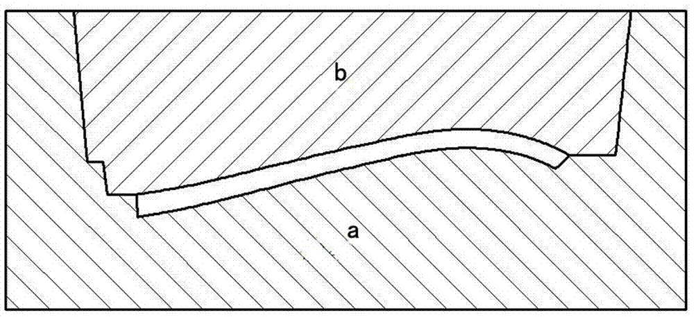
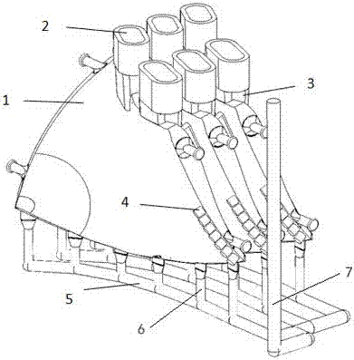
[0029] Such as image 3 — Figure 7 As shown, it is an embodiment of the sand core structure of the water turbine blade steel casting of the present invention, including several sand cores 8 that are sequentially assembled and combined along the straight line direction, such as Figure 4 and Figure 5 As shown, each adjacent sand core 8 is molded to form a casting cavity, and each sand core 8 is assembled and combined in sequence to form a plurality of casting cavities respectively, and the periphery of each adjacent sand core 8 cavity contour is provided with a matching The assembled core head 9 is provided with a positioning structure, each sand core shares a set of pouring system, and the top of the sand core 8 is respectively provided with a riser feeding structure.

[0030] In the sand mold structure arranged in a linear array in this embodiment, except for the sand cores located at the front and rear positions, the two sides of each sand core 8 in the middle position r...

Embodiment 2

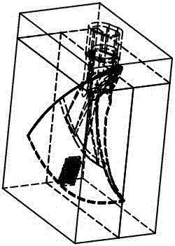
[0035] Such as Figure 8 Shown is the sand core structure of the water turbine blade steel castings of this embodiment that adopts the method of circular rotation array core assembly. The difference from the embodiment is that the sand cores of this embodiment are assembled sequentially along the circumferential direction to form a circular In the sand mold structure arranged in an array, the two sides of each sand core 8 also respectively form the front contour and reverse contour of the casting blade, and the circumference of the front contour and the reverse contour correspond to form the contour of the corresponding outer peripheral part of the blade. The matching and positioning structure of the head core between the sand cores is the same as that of the first embodiment, and the configuration of the pouring system and the riser feeding system is also similar to that of the first embodiment. The sand core structure of the circular rotating array of this structure can form...


PUM


Abstract

The invention relates to a sand core structure of water turbine blade steel castings in the technical field of casting. The sand core structure comprises a plurality of sand cores which are sequentially spliced and combined, and a casting cavity is formed after every two adjacent sand cores are combined. After the sand cores are sequentially spliced and combined, the multiple casting cavities are formed. Core heads spliced in a matched manner are arranged on the peripheries of the outlines of the adjacent sand core cavities. Each core head is provided with a positioning structure. The sand cores share one pouring system. A dead head feeding structure is arranged on the top of each sand core. According to the sand core structure of a water turbine blade, the beneficial effects that the water turbine blade plane size is large, and the thickness is small are utilized, one combined sand core structure is adopted, the multiple casting cavities are formed, one-time box burying modeling and one-time pouring are conducted to form the multiple castings, the sand-iron rate is greatly reduced, the thickness of single sand cores is reduced, and the overall casting technology efficiency is improved.

Description

technical field [0001] The invention relates to a sand mold casting process of steel castings in the technical field of casting, in particular to a sand core structure of steel castings of water turbine blades. Background technique [0002] Turbine blades are the key components of water turbine units, which have the characteristics of large curvature changes, thin walls, and large warpage. The traditional casting scheme is generally a real sample molding (also known as the flat impact vertical casting method) such as figure 1 As shown, or core molding (also known as vertical pouring method) scheme, such as figure 2 shown. [0003] Among them, the plan of horizontal collision and vertical pouring is as follows: figure 1 As shown, including sand mold a and sand core b, they are molded separately and then assembled in a box. The existing defects are: [0004] 1) It is necessary to process the real sample and support the tire plate; [0005] 2) After the sand core is assem...

Claims


Application Information

Patent Timeline
IPC IPC(8): B22C9/10B22C9/08
CPCB22C9/088B22C9/103
Inventor 苏志东唐钟雪
Owner KOCEL STEEL
Why Eureka
Try Eureka