
Impeller, draught fan and motor

A technology of impellers and blades, which is applied in the fields of impellers and fans with them, and motors, and can solve problems such as low performance and large fan volume

Pending Publication Date: 2017-09-08
GUANGDONG WELLING ELECTRIC MACHINE MFG +1
View PDF6 Cites 2 Cited by
  • Summary
  • Abstract
  • Description
  • Claims
  • Application Information

AI Technical Summary

Problems solved by technology

[0003] However, the vacuum cleaners in the prior art generally have the disadvantages of large fan volume and low performance, and it is necessary to continuously optimize the design of the impeller structure to further improve the working performance of the vacuum cleaner.

Method used


Image

  • Impeller, draught fan and motor
  • Impeller, draught fan and motor
  • Impeller, draught fan and motor

Examples


Embodiment Construction

[0039] Specific embodiments of the present invention will be described in detail below in conjunction with the accompanying drawings. It should be understood that the specific embodiments described here are only used to illustrate and explain the present invention, and are not intended to limit the present invention.

[0040] It should be noted that, in the case of no conflict, the embodiments of the present invention and the features in the embodiments can be combined with each other.

[0041] In the present invention, unless stated to the contrary, the used orientation words such as "up, down, top, bottom" generally refer to the directions shown in the drawings or refer to the vertical, perpendicular or gravitational directions The terms used to describe the mutual positional relationship of the various components mentioned above.

[0042] The present invention will be described in detail below with reference to the accompanying drawings and examples.

[0043] Such as Fi...


PUM


Abstract

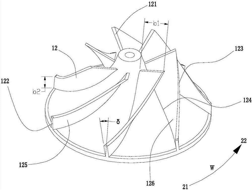
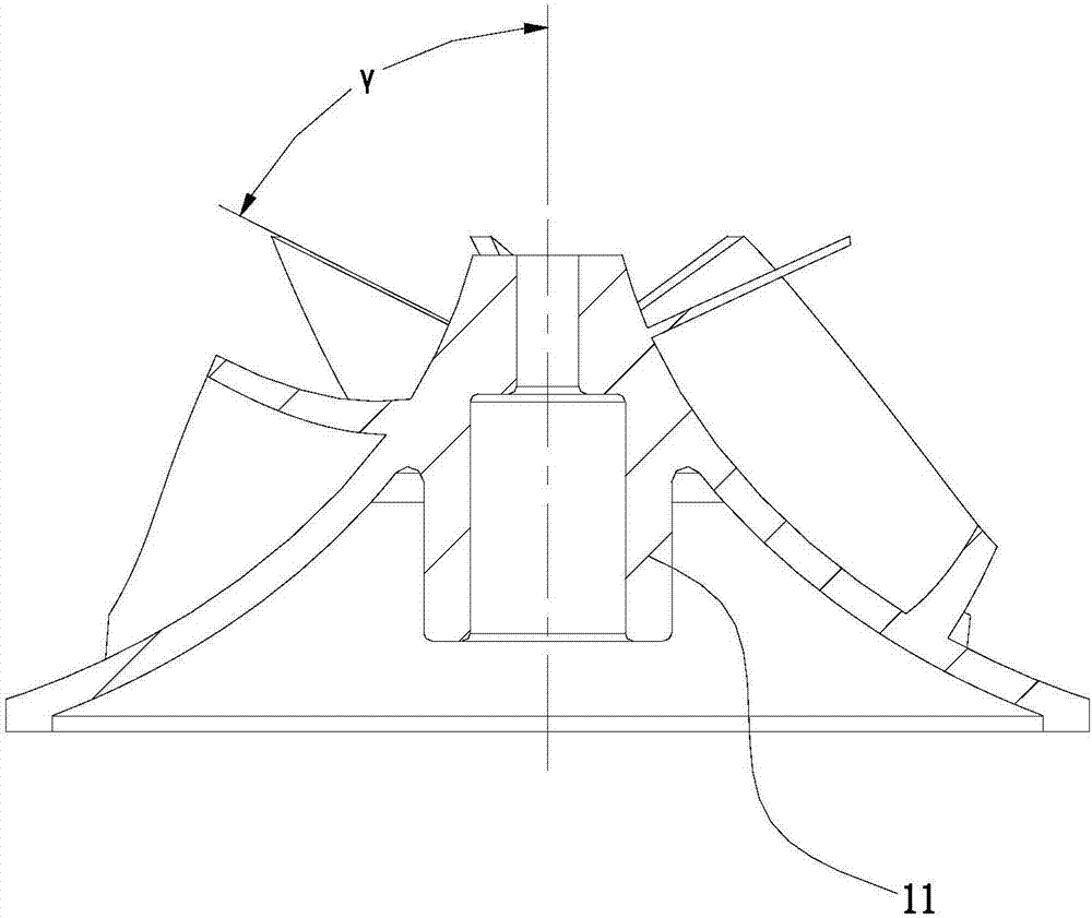
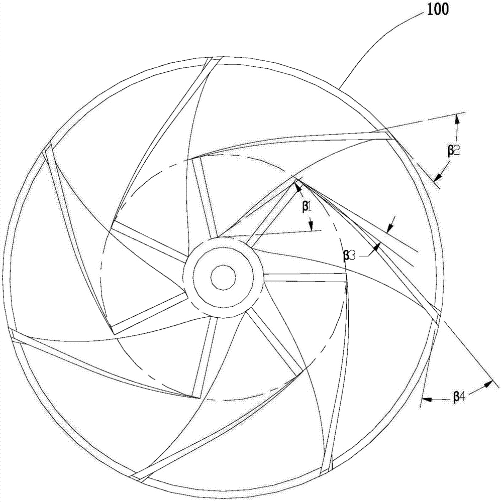
The invention discloses an impeller, a draught fan and a motor; the impeller (100) comprises a roughly-conical hub (11) and multiple blades (12) which are arranged on the outer circumference of the hub (11) at intervals in the circumferential direction; each blade comprises a front edge face on the inlet end and a rear edge face on the outlet end, the blades are flat plate twisted blades, and the blade front edge segments and the blade rear edge segments incline in a rotary twisted manner in the opposite directions in the circumferential direction; according to the impeller, the shape of the blades is optimized and designed, particularly, due to the fact that the blade front edge segments and the blade rear edge segments incline in the rotary twisted manner, convex faces and concave faces are formed on the same side faces of the blade front edge segments and the blade rear edge segments, fluid losses of the inlet ends and the outlet ends of the blades can be effectively reduced, the effective work range of the impeller is widened, and the work performance of the impeller is greatly improved.

Description

technical field [0001] The invention belongs to the field of impellers, and more specifically relates to an impeller and a fan and a motor with the same. Background technique [0002] In the vacuum cleaner, the motor drives the impeller to rotate at a high speed to form a negative pressure environment in the sealed housing, so that dust and the like are sucked into the dust collection device, so as to achieve the cleaning effect. Among them, the moving impeller is a key component of the vacuum cleaner, and its performance directly determines the overall working efficiency of the fan system. [0003] However, vacuum cleaners in the prior art generally have the disadvantages of large fan volume and low performance, and it is necessary to continuously optimize the design of the impeller structure to further improve the working performance of the vacuum cleaner. Contents of the invention [0004] In view of the above defects or deficiencies in the prior art, the present inven...

Claims


Application Information

Patent Timeline
IPC IPC(8): F04D29/28F04D29/30
CPCF04D29/28F04D29/281F04D29/30
Inventor 蒋婷婷冯国平
Owner GUANGDONG WELLING ELECTRIC MACHINE MFG
Learn More