Beam spot automatic corrector of accelerator and accelerator

A technology of orthotics and accelerators, applied in accelerators, electrical components, etc., can solve the problems of cumbersome steps, high difficulty in operation, and many manpower, and achieve the effect of simple steps and low difficulty in operation

Active Publication Date: 2017-09-08
CGN DASHENG ELECTRON ACCELERATOR TECH
View PDF10 Cites 5 Cited by
  • Summary
  • Abstract
  • Description
  • Claims
  • Application Information

AI Technical Summary

Problems solved by technology

Since there is only one pair of coils in the prior art, after realizing the correction of the beam spot on the X-axis, if the correction on the Y-axis is to be realized, the direction of the coils needs to be adjusted, and in the prior art it is manually adjusted Coils, on the one hand, have cumbersome steps, are difficult to operate, and require certain technical knowledge to operate; on the other hand, they consume more manpower, have large errors and reduce the working efficiency of the accelerator.

Method used


Image

  • Beam spot automatic corrector of accelerator and accelerator
  • Beam spot automatic corrector of accelerator and accelerator
  • Beam spot automatic corrector of accelerator and accelerator

Examples


Embodiment Construction

[0026] The core of the present invention is to provide an automatic beam spot corrector for an accelerator and an accelerator. On the one hand, the steps are simple and the operation difficulty is low;

[0027] In order to make the purpose, technical solutions and advantages of the embodiments of the present invention clearer, the technical solutions in the embodiments of the present invention will be clearly and completely described below in conjunction with the drawings in the embodiments of the present invention. Obviously, the described embodiments It is a part of embodiments of the present invention, but not all embodiments. Based on the embodiments of the present invention, all other embodiments obtained by persons of ordinary skill in the art without making creative efforts belong to the protection scope of the present invention.

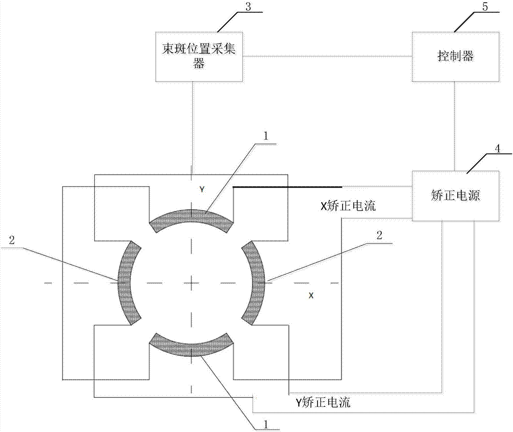
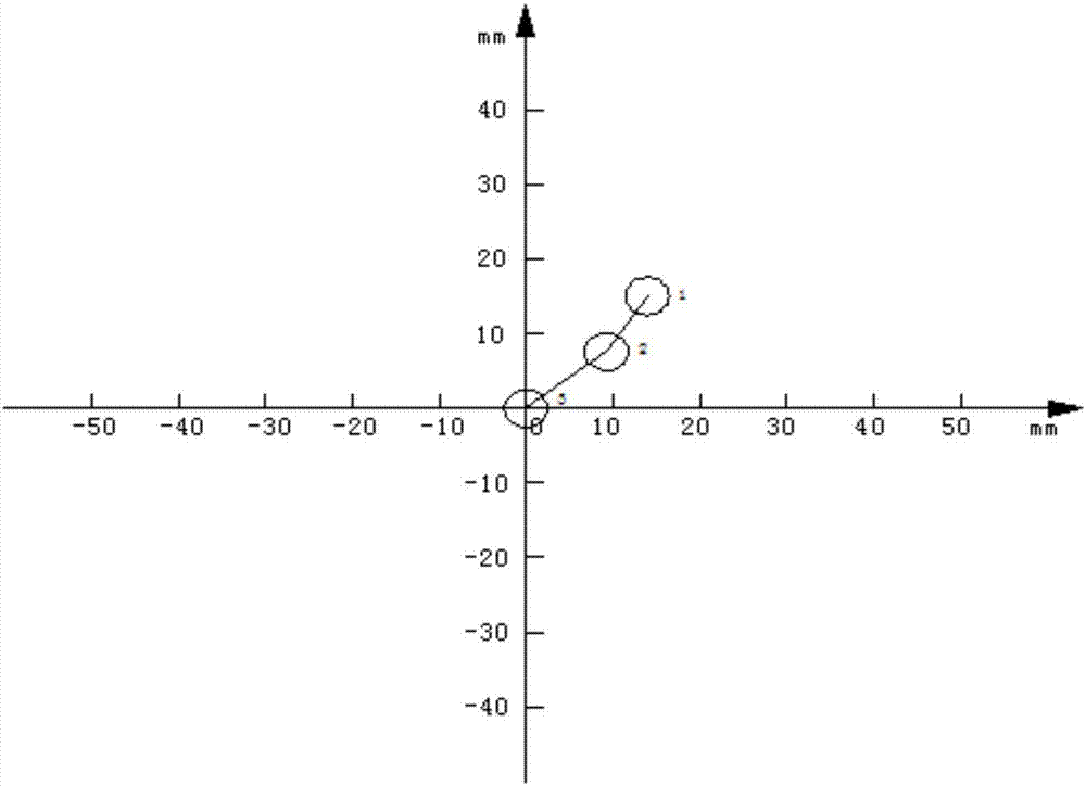
[0028] Please refer to figure 2 and image 3 ,in, figure 2 It is a schematic structural diagram of an accelerator beam spot automatic c...


PUM


Abstract

The invention discloses a beam spot automatic corrector of an accelerator and the accelerator. The beam spot automatic corrector comprises a pair of X coils, a pair of Y coils, a correction power supply, a beam spot position collector and a controller, the X coils and the Y coils are arranged on a drift tube and along the Y-axis direction and the X-axis direction of a coordinate system which regards an extraction window as a coordinate plane and the absolute center of the extraction window as the origin, a first output terminal of the correction power supply is connected with the X coils, a second output terminal of the correction power supply is connected with the Y coils, the beam spot position collector is used for acquiring the position of the beam spot on the extraction window, and the controller is used for determining X correction current and Y correction current corresponding to the position of the beam spot according to a preset relation table and controlling the correction power supply to output the X correction current to the X coils and to output the Y correction current to the Y coils in order to adjust the position of the beam spot until the position of the beam spot is at the absolute center of the extraction window. According to the beam spot automatic corrector of the accelerator and the accelerator, the steps are simple, the operation difficulty low, the consumption of a lot of manpower is avoided, the error is small, and the work efficiency of the accelerator is improved.

Description

technical field [0001] The invention relates to the technical field of accelerators, in particular to an accelerator beam spot automatic corrector and an accelerator. Background technique [0002] Please refer to figure 1 , figure 1 Schematic diagram of the structure of the accelerator beam channel. After the electron flow emitted by the electron gun in the accelerator passes through the accelerating tube, drift tube and focuser (both the focuser and the corrector are set in the drift tube), if it is not corrected by the corrector, the beam spot of the electron current may not be drawn out. The condition of the absolute center of the window cannot meet the operating conditions of the accelerator equipment. Therefore, it is necessary to use a rectifier in the accelerator to correct the beam spot of the electron flow to the absolute center of the extraction window. [0003] The rectifier in the prior art only includes a pair of X coils with the extraction window as the coor...

Claims


Application Information

Patent Timeline
Patent Type & Authority Applications(China)
IPC IPC(8): H05H7/00
CPCH05H7/001H05H2007/002Y02P10/25
Inventor 许森飞肖珺胡志荣陆洁平
Owner CGN DASHENG ELECTRON ACCELERATOR TECH
Why Eureka
Try Eureka