Water cooling device

A water-cooling heat dissipation and water-cooling technology, which is applied in the direction of cooling/ventilation/heating transformation, circuits, electrical components, etc., can solve the problems of the overall heat dissipation effect of the water-cooling heat sink, unfavorable space use and design, and reduced pump efficiency, etc., to achieve improvement and change performance and water volume, improve heat dissipation performance, and improve the effect of space utilization

Active Publication Date: 2017-09-08
AURAS TECH
View PDF10 Cites 10 Cited by
  • Summary
  • Abstract
  • Description
  • Claims
  • Application Information

AI Technical Summary

Problems solved by technology

However, when the pump itself is in operation, it will generate heat energy, which indirectly increases the heat source that should be dissipated in this area.
[0005] Moreover, if the heat energy generated by the pump is not properly discharged during operation, it will also reduce the efficiency of the pump, so that the overall heat dissipation effect of the water-cooled heat sink cannot be as good as imagined
[0006] Furthermore, the installation position of the pump on the existing water-cooling system is also limited by the available space inside the object to be radiated, which is not conducive to the use and design of space.

Method used


Image

  • Water cooling device
  • Water cooling device
  • Water cooling device

Examples


Embodiment Construction

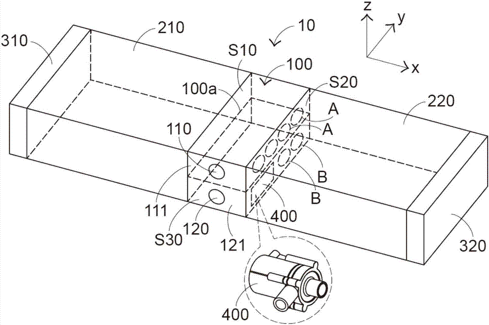
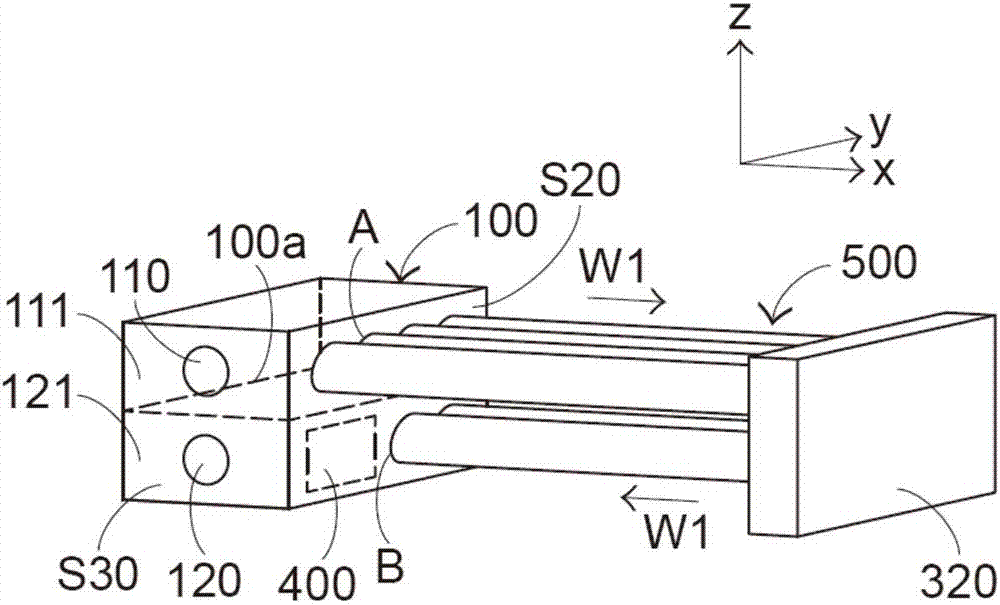
[0057] First of all, please refer to the three-axis directions shown in the figures. Here, it is assumed that the X-axis direction is the left-right direction of the water-cooling and heating device of the present invention, the Y-axis direction is the front-rear direction of the water-cooling and heating device, and the Z-axis direction is The up and down direction of the water cooling and heating device.

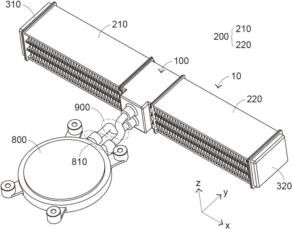
[0058] see Figure 1A to Figure 1D , Figure 1A A three-dimensional schematic diagram of the first embodiment of the basic inventive concept of collocating a water-cooled head for the water-cooled heat dissipation device of the present invention.

[0059] like Figure 1A to Figure 1D As shown, the water cooling system using the water cooling device of the present invention includes a water cooling head 800 , two water pipes 900 and a water cooling device 10 , and the water cooling device 10 communicates with the water cooling head 800 through the two water pipes 900 . Wh...


PUM


Abstract

A water cooling device includes a communication structure, a water cooling structure and a driving device. The communication structure includes a first chamber and a second chamber. The water cooling structure includes plural water tubes. The driving device is installed in at least one of the first chamber and the second chamber. The first chamber includes a water inlet and plural inlet ports. The second chamber comprises a water outlet and plural outlet ports. The water inlet and the water outlet are formed in the same lateral surface of the communication structure. At least two additional lateral surfaces of the communication structure are located beside the water cooling structure. The plural water tubes are in communication with the plural inlet ports and the plural outlet ports. A cooling medium is guided to flow through the plural water tubes. The water cooling device can prevent the generated heat of the driving device from diffusing to the heat dissipation region while effectively increasing the space utilization of the overall water cooling system.

Description

technical field [0001] The present invention relates to a water-cooling heat dissipation device, in particular to a water-cooling heat dissipation device that can effectively improve overall space utilization and heat dissipation performance. Background technique [0002] With the improvement of the performance of electronic products, the internal integrated circuit structure is becoming more and more complex, and with it, the heat energy of electronic products is getting higher and higher. If the heat energy cannot be dissipated in real time, the integrated circuit inside the packaged chip may be burned. Therefore, the performance of heat dissipation must be improved to maintain the normal operation of the chip. [0003] Compared with various heat dissipation structures applied to electronic products, one of them is a water-cooled heat dissipation structure. It uses liquid to take heat energy away from the chip, and then conducts heat exchange with air to dissipate the ab...

Claims


Application Information

Patent Timeline
Patent Type & Authority Applications(China)
IPC IPC(8): H05K7/20
CPCH05K7/20272H01L23/473H05K7/20263H05K7/20281
Inventor 吴安智范牧树陈建佑苏建志
Owner AURAS TECH
Why Eureka
Try Eureka