
Externally-mounted connector of airplane wing

A wing and joint technology, applied in the field of aircraft structure design, can solve the problems of unsatisfactory rigidity, complex structure, poor maintainability, etc., and achieve the effects of reducing production cost, simple disassembly, and simple structure

Inactive Publication Date: 2017-09-12
XIAN AIRCRAFT DESIGN INST OF AVIATION IND OF CHINA
View PDF0 Cites 0 Cited by
  • Summary
  • Abstract
  • Description
  • Claims
  • Application Information

AI Technical Summary

Problems solved by technology

[0003] The purpose of the present invention is to provide a wing external joint, which solves the problems of the current connecting joints or complex structures, poor maintainability, or rigidity that does not meet the requirements

Method used


Image

  • Externally-mounted connector of airplane wing
  • Externally-mounted connector of airplane wing

Examples


Embodiment Construction

[0013] In order to make the objectives, technical solutions and advantages of the present invention clearer, the technical solutions in the embodiments of the present invention will be described in more detail below with reference to the accompanying drawings in the embodiments of the present invention. Throughout the drawings, the same or similar reference numbers refer to the same or similar elements or elements having the same or similar functions. The described embodiments are some, but not all, of the embodiments of the present invention. The embodiments described below with reference to the accompanying drawings are exemplary, and are intended to explain the present invention, and should not be construed as limiting the present invention. Based on the embodiments of the present invention, all other embodiments obtained by those of ordinary skill in the art without creative work fall within the protection scope of the present invention. The embodiments of the present inv...


PUM


Abstract

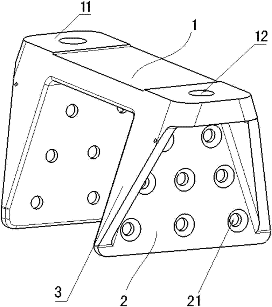
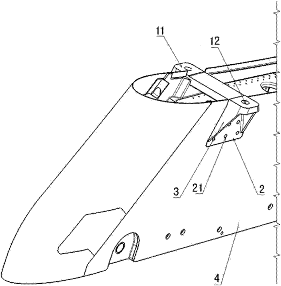
The invention relates to a wing external joint. The wing external joint includes a horizontal plate and a side wall. There are two side walls. The two side walls are placed at both ends of the horizontal plate and the two The wall is located on the same side of the horizontal plate, and bosses are provided at both ends of the horizontal plate, and the bosses are located on the opposite side of the side wall, and a first connecting hole is provided through the boss, and on both sides A plurality of second connection holes are provided on the walls, the wing external joint is connected to the wing through the first connection holes, and the wing external joint is connected to the transition beam through the second connection holes. The external wing joint of the invention has a simple structure, greatly reduces the number of parts, and reduces the production cost; it is easy to disassemble and is convenient for maintenance in the future; the structural strength is improved and meets the use requirements.

Description

technical field [0001] The invention belongs to the field of aircraft structure design, and in particular relates to a wing external hanging joint. Background technique [0002] The aircraft wing is one of the important parts of the aircraft. Its main function is to generate lift. Usually, a suspension device is installed under the wing. According to the development of the aircraft, a suspension device is added under the wing, and the transition beam is required to be able to achieve universal, interchangeable and Quick unload. Therefore, it is necessary to carry out a new design of the general transition beam, and to improve the adaptability and strengthen the design of each station of the wing, so the design of the wing external joint is particularly important. The structural strengthening design of a certain type of aircraft wing, in simple terms, is to strengthen the design of the wing box so that it can meet the installation and suspension of general transition beams a...

Claims


Application Information

Patent Timeline
Patent Type & Authority Applications(China)
IPC IPC(8): B64C3/00
CPCB64C3/00
Inventor 魏敏楠秦赟纠永军苗志敏姚建成
Owner XIAN AIRCRAFT DESIGN INST OF AVIATION IND OF CHINA
Learn More