Eureka AIR delivers breakthrough ideas for toughest innovation challenges, trusted by R&D personnel around the world.

Ventilator

A ventilation device and exhaust chamber technology, applied in the direction of shielding with air flow, control input related to air characteristics, ventilation system, etc., can solve the problems of large device size, increased cost, air pollution, etc., and increase the number of rotations , prevent condensation, reduce volume effect

Active Publication Date: 2020-05-05
KYUNGDONG NAVIEN
View PDF8 Cites 0 Cited by
  • Summary
  • Abstract
  • Description
  • Claims
  • Application Information

AI Technical Summary

Problems solved by technology

This kind of external air cooling is usually performed during the season change in spring or autumn, and is not used in winter. However, when the bypass mode is not used, the air will stagnate in the bypass channel, resulting in condensation and air pollution. So there is a problem of causing bacteria to multiply
[0011] In addition, Korean Patent No. 10-0577252 discloses an air purification and ventilation system with both air purification and ventilation functions. However, since the ventilation device and the air purification device are relatively independent, there is a device The problem of larger size and increased cost

Method used


Image

  • Ventilator
  • Ventilator
  • Ventilator

Examples


Embodiment Construction

[0059] Hereinafter, the configuration and operation of preferred embodiments according to the present invention will be described in detail with reference to the accompanying drawings.

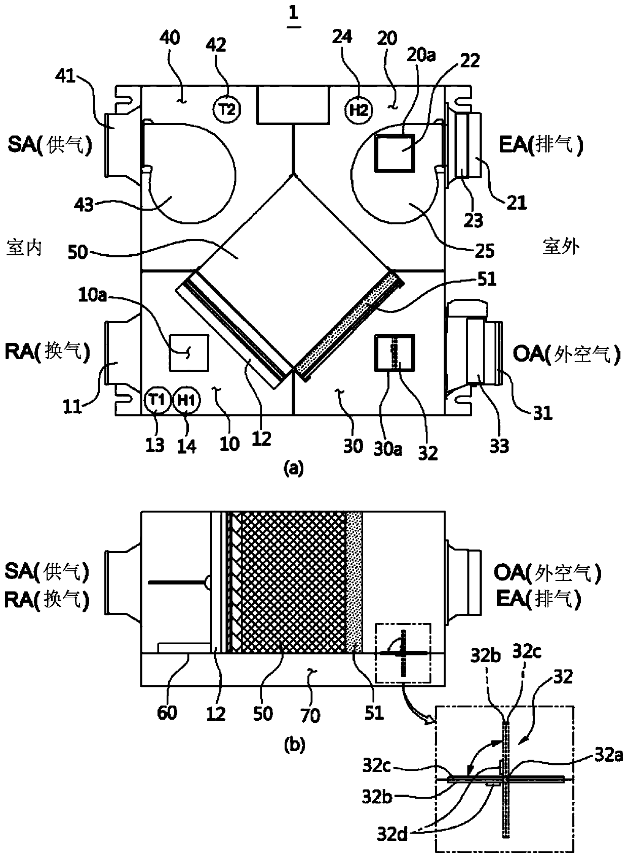
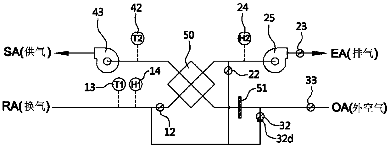
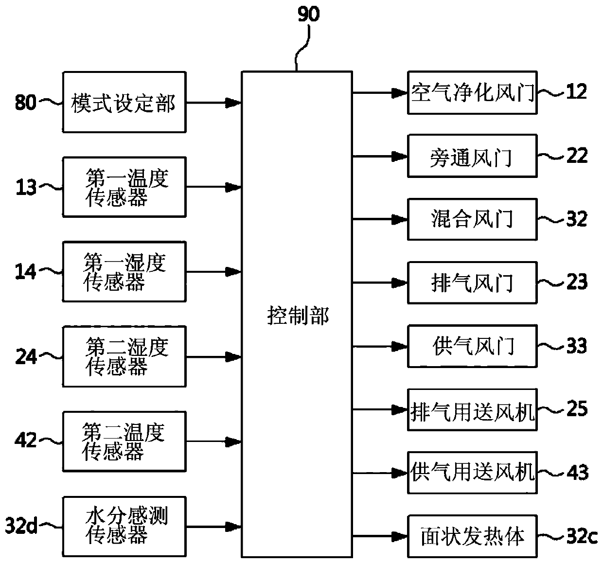
[0060] refer to Figure 1 to Figure 3 According to an embodiment of the present invention, the ventilating device 1 includes: a first exhaust chamber 10, into which indoor air flows; a second exhaust chamber 20, used for discharging to the outside through the first exhaust chamber 10; The indoor air of an exhaust chamber 10; the first air supply chamber 30, the outdoor air flows into the first air supply chamber 30; the second air supply chamber 40 is used to pass the outdoor air through the first air supply chamber supply to the room; the total heat exchanger 50 realizes the indoor air flowing from the first exhaust chamber 10 to the second exhaust chamber 20 and the indoor air flowing from the second exhaust chamber 20 to the first exhaust chamber 10 Heat exchange between outdoor air. More...


PUM


Abstract

The invention provides a ventilator. Occurrence of dew condensation is effectively avoided in the interior and exterior of a device; ventilation quantity required by indoor persons is fully met; energy efficiency is maximized; and especially, positive pressure is always kept indoors and pollution from the outside is avoided. The ventilator is characterized in that one side of a first air exhausting chamber, one side of a second air exhausting chamber, one side of a first air supplying chamber, one side of a second air supplying chamber and one side of a full heat exchanger are separated from each other through separation plates so that bypass channels are formed. The bypass channels provide flow passages through which indoor air flowing into the first air exhausting chamber flows to the second air exhausting chamber without passing through the full heat exchanger under a bypass mode, provide flow passages through which all indoor air flowing into the first air exhausting chamber flows towards the side of the first air supplying chamber under an air purifying mode, and provide paths for flowing towards the first air supplying chamber under a dew condensation control model so as to allow all of or one part of indoor air flowing into the first air exhausting chamber to be mixed with the indoor air flowing to the first air supplying chamber.

Description

technical field [0001] The present invention relates to a ventilator, and more specifically, to a ventilator that mixes and recirculates air introduced into a room from the outside with indoor air to prevent dew condensation from occurring inside and outside the device, and at the same time It can meet the required air exchange volume inside the room, and can maximize energy efficiency, especially by keeping the room at a positive pressure to prevent pollution caused by the outside. Background technique [0002] General homes and offices are equipped with cooling and heating devices to perform indoor cooling and heating based on seasonal changes, and such cooling and heating devices include air conditioners for cooling and heating air by cooling and heating. , Stove, etc. [0003] In order to improve cooling and heating efficiency, the indoors of general homes and offices equipped with the above-mentioned cooling and heating devices are kept closed, and the closed indoor sp...

Claims


Application Information

Patent Timeline
Patent Type & Authority Patents(China)
IPC IPC(8): F24F7/007F24F11/89F24F11/64F24F12/00F24F13/28F24F13/30F24F110/10F24F110/20
CPCF24F7/007F24F11/0001F24F12/006F24F13/28F24F13/30F24F2012/007
Inventor 李基成
Owner KYUNGDONG NAVIEN
Why Eureka
Eureka Blog
Learn More