Eureka AIR delivers breakthrough ideas for toughest innovation challenges, trusted by R&D personnel around the world.

System for automatically controlling water diversion

An automatic control system and water diversion pipe technology, applied in the control/adjustment system, non-electric variable control, flow control, etc., can solve the problems of unable to meet the stability requirements of water areas, unable to achieve punctuality, measurement and calculation errors, etc., to achieve Good promotion and application value, convenient and timely water diversion process, low-demand effect

Pending Publication Date: 2017-09-12
CHINA RAILWAY 16TH BUREAU GRP CO LTD +1
View PDF8 Cites 3 Cited by
  • Summary
  • Abstract
  • Description
  • Claims
  • Application Information

AI Technical Summary

Problems solved by technology

The water system in the southern part of my country is developed, and there are many lakes and rivers converging and flowing. The river channel relocation is mostly used for small river tributaries. During the relocation process, if the open channel water diversion method is used, although a better water diversion effect can be achieved, the relocation process is labor-intensive and time-consuming. , the cost is high, and the relocation of the river is mostly a temporary project, and the construction site is limited, so it is not easy to implement; while the method of water diversion using ordinary pumping pipelines has low construction costs and a small site occupancy rate, but it measures the water source in the river After the flow rate, the state of the water pump is controlled and a series of operations to adjust the diversion flow are done manually, which cannot achieve the effect of punctuality, and there are large errors in the measurement and calculation of man-made during the measurement process, which cannot meet the stability of the water area. Require

Method used


Image

  • System for automatically controlling water diversion
  • System for automatically controlling water diversion
  • System for automatically controlling water diversion

Examples


no. 1 example

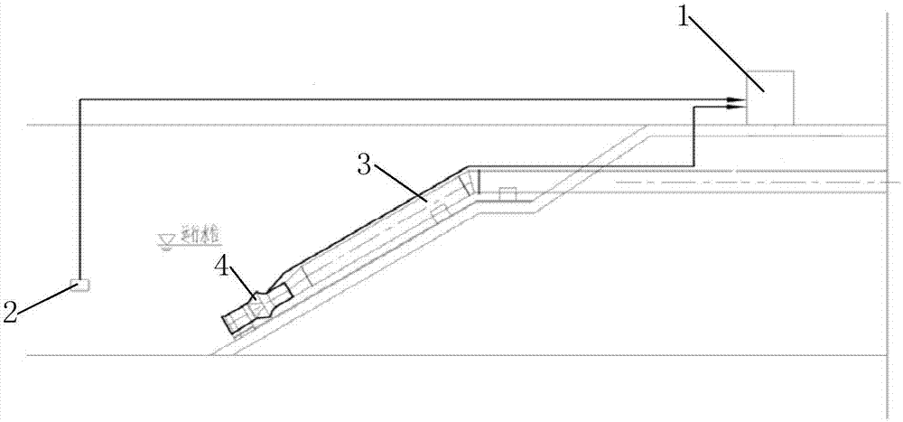
[0044] figure 1 It is a structural schematic diagram showing the first embodiment of the temporary water diversion automatic control system provided by the present invention.

[0045] Such as figure 1 As shown, the temporary water diversion automatic control system has a water diversion device, a central control processor 1 and an electromagnetic flow meter 2 as a water source flow rate monitoring device arranged in the water source.

[0046] In detail, the water diversion device includes a water diversion pipeline 3 and three water pumps 4, the three water pumps 4 include a first water pump, a second water pump and a third water pump whose rated flow increases in sequence, and each water pump 4 is connected in parallel with each other. Connect with the water inlet of the diversion pipeline 3.

[0047] The electromagnetic flow meter 2 and each water pump 4 are respectively electrically connected to the central control processor 1 , and the central control processor 1 control...

no. 2 example

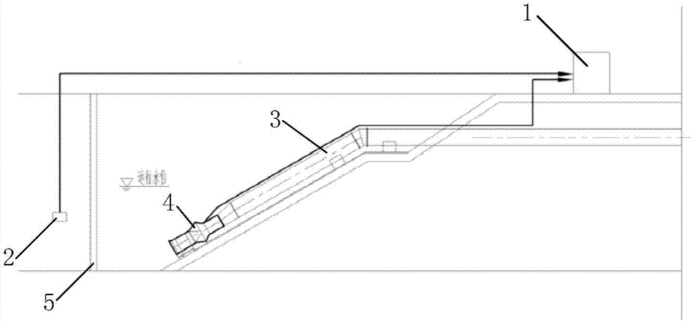
[0051] figure 2 It is a structural schematic diagram showing the second embodiment of the temporary water diversion automatic control system provided by the present invention.

[0052] Such as figure 2 As shown, on the basis of the above-mentioned first embodiment, a grid 5 is added at the upstream of the water pump 4 in the water source, and the grid 5 is arranged between the electromagnetic flow meter 2 and each water pump 4, and the grid 5 and each water pump 4 A distance is reserved between the water pumps 4 .

no. 3 example

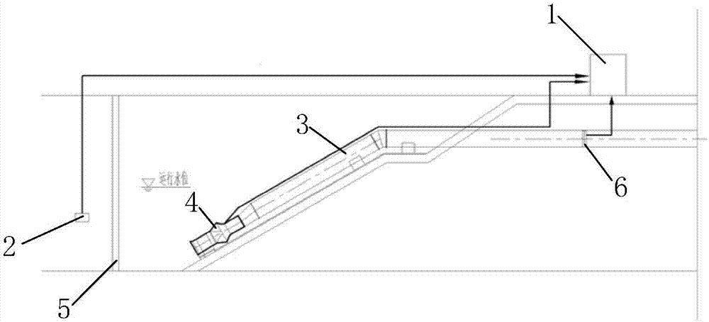
[0054] image 3 It is a structural schematic diagram showing the third embodiment of the temporary water diversion automatic control system provided by the present invention. Figure 4 It represents the sectional view at the water outlet of the water diversion pipe of the third embodiment of the temporary water diversion automatic control system provided by the present invention.

[0055] Such as image 3 and Figure 4 As shown, on the basis of the above-mentioned second embodiment, an electromagnetic flowmeter 6 as a diversion flow monitoring device is added at the water outlet of the diversion pipeline 3 to measure the diversion flow of the diversion pipeline 3, and the electromagnetic flowmeter 6 The flow meter 6 is electrically connected with the central control processor 1 .

[0056] At this time, the central control processor 1 also has an information receiving and transmitting unit and an information processing control unit connected to each other,

[0057] However,...


PUM


Abstract

The invention relates to a system for automatically controlling temporary water diversion. The system comprises a water diversion device, a central control processor and a water source flow velocity monitoring device arranged in a water source; the water diversion device comprises a water diversion pipeline and at least two water pumps connected with a water inlet of the water diversion pipeline; the water pumps are connected in parallel; the water source flow velocity monitoring device and the water pumps are electrically connected with the central control processor respectively; and the central control processor controls start and stop states of each water pump according to information transmitted by the water source flow velocity monitoring device. The system for automatically controlling temporary water diversion, provided by the invention, can be applied to river channel dredging engineering and can automatically control and regulate the water division flow according to the flow velocity of the water source in a river channel to achieve the technical effect of stabilizing water diversion.

Description

technical field [0001] The invention relates to the field of river dredging engineering in municipal engineering, in particular to an automatic control system for temporary water diversion. Background technique [0002] Municipal engineering involves the construction of various public transportation facilities, water supply, drainage, gas, urban flood control, environmental sanitation and lighting, and is an essential material basis for urban survival and development. [0003] Among them, because the river not only undertakes the task of discharging floods in the flood season and regional water production, but also undertakes the task of diverting and exchanging regional water. If the river channel is blocked and cannot communicate, it will affect a large area around it, and the rainfall and water produced in this area will not be drained naturally. Therefore, it is necessary to divert and relocate the river channel through the river channel reconstruction project in the mun...

Claims


Application Information

Patent Timeline
IPC IPC(8): G05D7/06
CPCG05D7/0688
Inventor 范志高程传过王军飞程雨池屈庆旭贾琼陈晓东王宁郑玥杭翔
Owner CHINA RAILWAY 16TH BUREAU GRP CO LTD
Why Eureka
Eureka Blog
Learn More