Multi-antenna control method and system, and intelligent equipment

A technology of intelligent equipment and control method, applied to antennas, electrical components, etc., can solve the problems of energy waste, output power drop, waste of antenna communication resources, etc., and achieve the effect of increasing communication radius, increasing output power, and improving communication distance.

Inactive Publication Date: 2017-09-12
POWERVISION TECH
View PDF3 Cites 16 Cited by
  • Summary
  • Abstract
  • Description
  • Claims
  • Application Information

AI Technical Summary

Problems solved by technology

This causes a waste of antenna communication resources. Moreover, due to the limited output power of the UAV, when multiple antennas work at the same time, the output energy will be divided equally, and the output power of each antenna will decrease.
The weight of multiple antennas will increase the weight of the UAV itself, and at the same time reduce the load weight of the UAV, which will cause difficulties for the miniaturization o

Method used


Image

  • Multi-antenna control method and system, and intelligent equipment
  • Multi-antenna control method and system, and intelligent equipment
  • Multi-antenna control method and system, and intelligent equipment

Examples


Example Embodiment

[0058] Example one

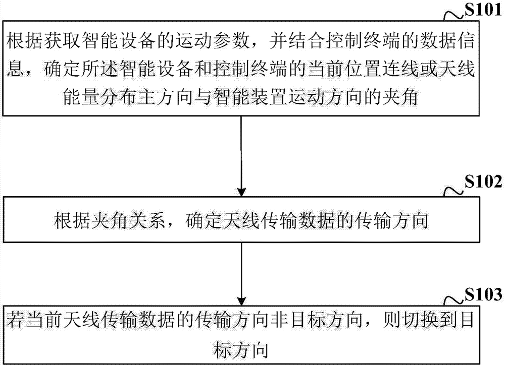
[0059] Such as figure 1 As shown, this embodiment provides an antenna control method, and the specific implementation method includes:

[0060] S101: According to the acquired motion parameters of the smart device and combined with the data information of the control terminal, determine the angle between the current position connection or the main direction of energy distribution of the smart device and the control terminal and the motion direction of the smart device;

[0061] The antenna control method provided by the embodiment of the present invention is applied to an unmanned aerial vehicle. The unmanned aerial vehicle is a multi-antenna unmanned aerial vehicle. Two or more antennas on the unmanned aerial vehicle are distributed at an angle and their working range covers unmanned aerial vehicles. The 360° whole body of the machine. The data information of the control terminal includes positioning coordinate data, sensor data, and antenna data of the control...

Example Embodiment

[0072] Example two

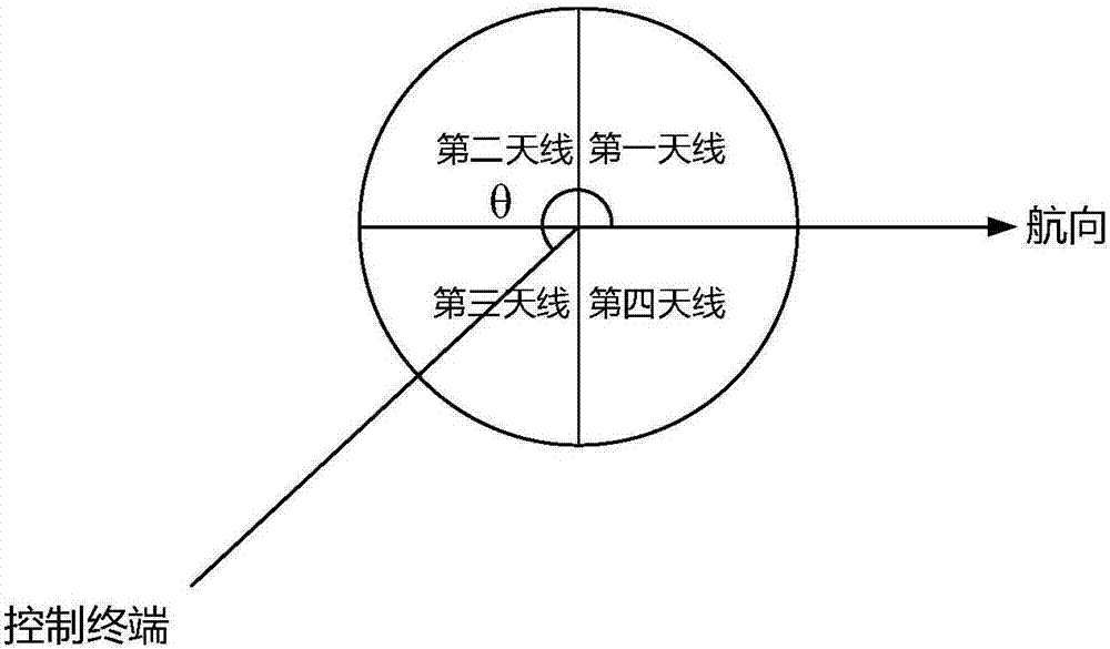
[0073] This embodiment is an antenna control method, and 4 antennas are provided on the drone.

[0074] S1: Determine the angle between the current position connection of the drone and the control terminal and the heading of the drone according to the acquired motion parameters of the drone, combined with the data information of the control terminal;

[0075] S2: Determine the transmission direction of data transmitted by the antenna on the drone according to the included angle;

[0076] S3: If the data transmission direction of the current antenna is not the target direction, start the antenna in the target direction and turn off the current working antenna.

[0077] The movement parameters of the drone include the positioning coordinates, heading, movement speed, and movement height of the drone; the positioning coordinates are obtained by the GPS device on the drone, and the current heading of the drone is obtained by a magnetic compass. The movement speed is ob...

Example Embodiment

[0094] Example three

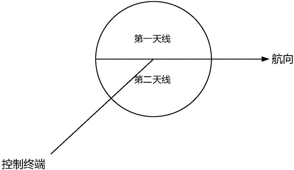
[0095] This embodiment is another antenna control method, such as Figure 5 As shown, there are two antennas on the drone.

[0096] S1: Determine the angle between the current position of the drone and the control terminal and the drone's heading based on the acquired motion parameters of the drone, combined with the data information of the control terminal;

[0097] S2: Determine the transmission direction of the antenna to transmit data according to the included angle;

[0098] S3: If the current transmission direction of the data transmitted by the antenna is not the target direction, switch the electromagnetic wave phase of the antenna to the target direction.

[0099] The movement parameters of the drone include the positioning coordinates, heading, movement speed, and movement height of the drone; the positioning coordinates are obtained by the GPS device on the drone, and the current heading of the drone is obtained by a magnetic compass. The movement spee...


PUM


Abstract

The invention relates to an antenna control method. The antenna control method is characterized in that the antenna control method is applied to intelligent equipment, a motion parameter of the intelligent equipment is acquired, in combination with the data information of a control terminal, the present position connection line of the intelligent equipment and the control terminal or an included angle of a main antenna energy distribution direction and an intelligent equipment motion direction is determined; according to the included angle, a transmission direction of antenna transmission data is determined; if the transmission direction of the antenna transmission data is not a target direction, the transmission direction is switched to the target direction. The method is advantaged in that on the condition that communication coverage of the intelligent equipment is not reduced, the quantity of antenna units forming an antenna array is reduced, self weight of the intelligent equipment is reduced, endurance of the intelligent equipment is enhanced, service life of the antenna units borne by the intelligent equipment is prolonged to a certain degree, and thereby service life of the intelligent equipment is prolonged.

Description

technical field [0001] The invention belongs to the technical field of antennas, and in particular relates to an antenna control method, a control system and an intelligent device. Background technique [0002] Unmanned aerial vehicle, referred to as "drone", or "UAV" in English, is an unmanned aircraft controlled by radio remote control equipment and its own program control device. Antennas play an important role in drone transceivers. Its performance, especially directivity and efficiency directly affect the communication distance and the safety of the transmitter. According to the flight characteristics of UAV, for the communication antenna without servo, its pattern should be omnidirectional on the horizontal plane. Due to the limitation of the UAV load, the airborne antenna should be small in size and light in weight, and the influence of the shape on the flight performance of the UAV should be considered at the same time. UAV antennas can use omnidirectional antenna...

Claims


Application Information

Patent Timeline
IPC IPC(8): H01Q3/24
CPCH01Q3/24
Inventor 郑卫锋佩卡·萨洛宁
Owner POWERVISION TECH
Why Eureka
Try Eureka