Electric motor diagnosis device
A technology for diagnosing devices and motors, which is used in motor generator testing, AC motor control, measuring devices, etc., can solve the problems of large number of wirings and unrealistic application.
- Summary
- Abstract
- Description
- Claims
- Application Information
AI Technical Summary
Problems solved by technology
Method used
Image
Examples
Embodiment approach 1
[0033] Below, based on Figure 1 to Figure 7 The motor diagnostic device according to Embodiment 1 of the present invention will be described.
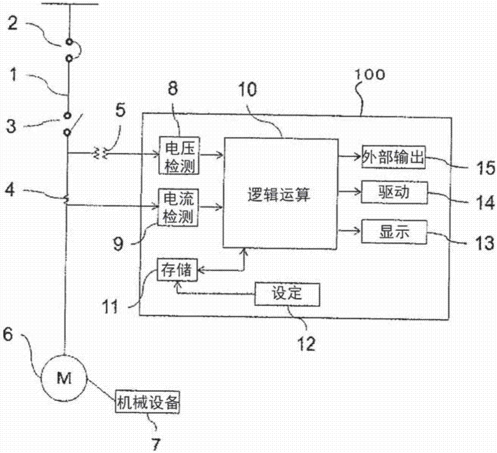
[0034] figure 1 It is a circuit diagram showing the configuration of the motor diagnostic device according to Embodiment 1 of the present invention, and is mainly used as a control center of an enclosed switchboard.
[0035] exist figure 1 In the main circuit 1 of the power source introduced from the power system, a circuit breaker 2 for wiring, an electromagnetic contactor 3, an instrument converter 4 for detecting the load current of the main circuit 1, and a circuit breaker for detecting the voltage of the main circuit 1 are provided. A transformer 5 for instrumentation is connected to a motor 6 as a load, and the motor 6 operates to drive a mechanical device 7 .
[0036] The motor diagnosis device 100 includes: a voltage detection circuit 8 connected to the meter transformer 5, a current detection circuit 9 connected to the met...
Embodiment approach 2
[0092] Next, based on Figure 8 A motor diagnostic device according to Embodiment 2 of the present invention will be described.
[0093] Figure 8 The flow chart showing the diagnostic processing of the second embodiment is the same as that of the first embodiment from step S1 to step S7, and thus description thereof will be omitted.
[0094] exist Figure 8 In step S8, the increase amount of the negative phase current Isn relative to the normal phase current Isp is compared with the threshold value δ2. In step S8, when the amount of increase of the negative phase current Isn relative to the normal phase current Isp is smaller than the threshold value δ2 (Yes), proceed to step S9.
[0095] In step S9, the evaluation value A=|Isn−Yn*Vsn| is compared with the threshold value δ1. When the evaluation value A is equal to or greater than the threshold value δ1 (Yes), it is determined that the winding is short-circuited, and when the evaluation value A is smaller than the thresho...
Embodiment approach 3
[0099] Next, a diagnosis device for a motor according to Embodiment 3 of the present invention will be described.
[0100] In Embodiments 1 and 2, one logic operation unit 10 is provided for each motor 6 , but in Embodiment 3, voltage and current signals are analyzed by one logic operation unit 10 for a plurality of motors to determine abnormality.
[0101] As a disadvantage of Embodiment 1, in the initial normal value storage, an abnormal value is stored for the first time in the case of a motor that has already failed. Therefore, by collectively processing the information of a plurality of motors, for example, in the case of the same motor, it is possible to determine whether it is normal or abnormal in the initial determination.
PUM
 Abstract
Description
Claims
Application Information
 - R&D
- Intellectual Property
- Life Sciences
- Materials
- Tech Scout
- Unparalleled Data Quality
- Higher Quality Content
- 60% Fewer Hallucinations
Browse by: Latest US Patents, China's latest patents, Technical Efficacy Thesaurus, Application Domain, Technology Topic, Popular Technical Reports.
© 2025 PatSnap. All rights reserved.Legal|Privacy policy|Modern Slavery Act Transparency Statement|Sitemap|About US| Contact US: help@patsnap.com


