Axial flow blood pump adopting split through-hole bearing structure

A split-type, bearing technology, applied in the field of medical devices, can solve the problems of high risk of thrombus formation, flow stagnation area, large contact area between static and rotational, and achieve the effect of reducing the risk of thrombus formation at the shaft end

Pending Publication Date: 2017-09-15
FUWAI HOSPITAL CHINESE ACAD OF MEDICAL SCI & PEKING UNION MEDICAL COLLEGE
View PDF7 Cites 2 Cited by
  • Summary
  • Abstract
  • Description
  • Claims
  • Application Information

AI Technical Summary

Problems solved by technology

At present, axial flow blood pumps with shafts basically adopt sliding thrust bearing structure. The rotational and static contact area near the contact position between the mechanical bearing and the shaft is large, and the traditional sliding thrust bearing structure is easy to form blood flow dead zone or flow stagnation zone. , with the greatest risk of thrombosis, which has been confirmed by numerical analysis and animal experiments

Method used


Image

  • Axial flow blood pump adopting split through-hole bearing structure
  • Axial flow blood pump adopting split through-hole bearing structure
  • Axial flow blood pump adopting split through-hole bearing structure

Examples


Embodiment Construction

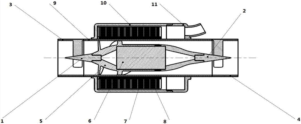
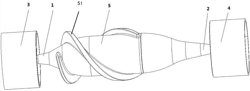
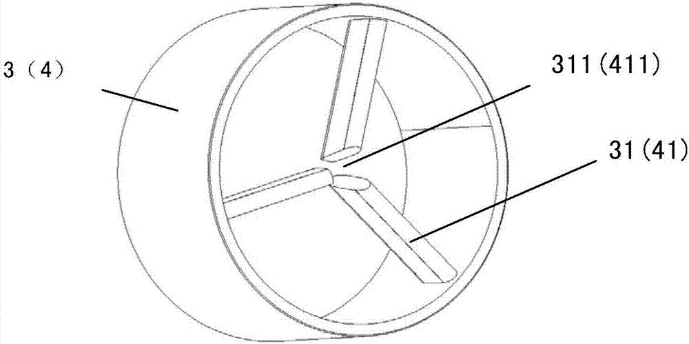
[0018] see figure 1 , figure 2 , image 3 , Figure 4 Shown: an axial flow blood pump adopting a split-type through-hole bearing structure, which includes a front casing 3, a rotor 6, a rotor casing 9 and a rear casing 4, the front casing 3 is circular, and the The circular inner wall of the front casing is uniformly connected with 3 straight blades 31, and the inner ends of the 3 straight blades are suspended to form the front axle hole 311. The rear casing 4 is circular, and the circular inner wall of the rear casing is uniform. There are three straight blades 41 integrally connected, and the inner ends of the three straight blades are suspended to form a rear shaft hole 411. Between the front casing 3 and the rear casing 4, a rotor casing 9 is integrally connected. The rotor casing 9 is a cylinder. shape, the inner diameter of the rotor casing 9 is the same as the inner diameter of the front casing 3 and the rear casing 4, and a rotor 6 is arranged in the rotor casing 9...


PUM


Abstract

The invention discloses an axial flow blood pump adopting a split through-hole bearing structure. The axial flow blood pump comprises a front cartridge, a rotor, a rotor cartridge and a rear cartridge; three straight blades are uniformly and integrally connected to the annular inner wall of the front cartridge, and the inner walls of the three straight blades are suspended, so that front axial holes are formed; three straight blades are uniformly and integrally connected to the annular inner wall of the rear cartridge, and the inner walls of the three straight blades are suspended, so that rear axial holes are formed; the rotor cartridge is integrally connected between the front cartridge and the rear cartridge; the rotor is arranged in the rotor cartridge; two rotating blades are arranged on the outer circumference of the rotor; and the two rotating blades, which are located between the rear half parts of the rotor, can promote obvious expansion of a runner. The axial flow blood pump provided by the invention has the beneficial effects that since the straight blades in the front cartridge and the rear cartridge, instead of bearings, can take a supporting effect, a rotary-static interface is eliminated; the split bearing structure is defined by the three independent blades; and blood can flow in gaps between front and rear jewel axles and the straight blades, so that a flowing dead zone is prevented and a risk of thrombosis at an axial end is effectively reduced.

Description

technical field [0001] The invention relates to the technical field of medical devices, in particular to an axial flow blood pump adopting a piece-type through-hole bearing structure. Background technique [0002] Currently, in the absence of heart transplant donors, installing a ventricular assist pump is an effective way to prolong the life of patients with heart failure. The ventricular assist blood pump can partially or completely replace the pumping function of the heart and maintain the necessary human blood circulation. Ventricular assisting blood pump has played an active role in heart failure, cardiogenic shock treatment, cardiopulmonary resuscitation, transitional support therapy before heart transplantation, and replacement therapy, and still has great application potential. At present, the mainstream of ventricular assist blood pumps is the rotary blood pump. The rotary blood pump is divided into two types: axial flow blood pump and centrifugal blood pump. Axial...

Claims


Application Information

Patent Timeline
Patent Type & Authority Applications(China)
IPC IPC(8): A61M1/12
CPCA61M60/818A61M60/122
Inventor 胡盛寿柳光茂陈海波周建业
Owner FUWAI HOSPITAL CHINESE ACAD OF MEDICAL SCI & PEKING UNION MEDICAL COLLEGE
Why Eureka
Try Eureka