Powder drive type fire extinguishing cannon

A fire extinguishing cannon and barrel technology, applied in the field of fire extinguishing cannon, can solve the problems of limited dry powder on the warhead, explosion around the fire point, and no high-rise fire, etc., to achieve the effect of reducing instantaneous momentum, reducing volume and weight, and being easy to carry

Inactive Publication Date: 2017-09-15
重庆国飞通用航空设备制造有限公司
View PDF6 Cites 2 Cited by
  • Summary
  • Abstract
  • Description
  • Claims
  • Application Information

AI Technical Summary

Problems solved by technology

[0002] Due to the limited lifting height of existing fire trucks, there is no effective way to extinguish high-rise fires. Therefore, many manufacturers are thinking of launching fire extinguishing bombs from the ground or drones to extinguish the fire, but because the launcher has requirements for the weight of the fire extinguishing bombs , so the dry powder limit of the warhead belt is limited, and the warhead does not necessarily explode around the fire point when it enters the house. At the same time, the shrapnel produced by the explosion of the warhead can easily cause harm to personnel.

Method used


Image

  • Powder drive type fire extinguishing cannon
  • Powder drive type fire extinguishing cannon
  • Powder drive type fire extinguishing cannon

Examples


Embodiment 1

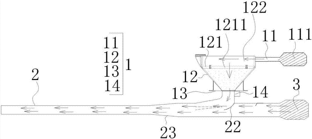
[0031] like figure 1 As shown, a powder-displacement type fire extinguisher includes a powder box 1, a gun barrel 2 and a main pressure source 3, such as figure 1 As shown, the main pressure source 3 is a ducted fan. The main pressure source 3 pressurizes the gun barrel 2 from the breech of the gun barrel 2, and the powder filling box 1 is fixed on the outer peripheral surface of the gun barrel 2;

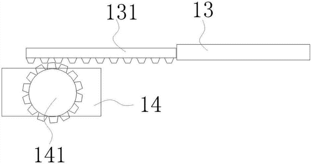
[0032] like figure 1 As shown, the powder filling box 1 includes an auxiliary pressurizing pipe 11, a box body 12, a flow control plate 13 and a steering gear 14, the auxiliary pressurizing pipe 11 communicates with the top of the box body 12, and the auxiliary pressurizing pipe 11 communicates with the top of the box body 12. The pressure pipe 11 communicates with an auxiliary pressure source 111, and the auxiliary pressure source 111 is a ducted fan. like figure 1 As shown, the box body 12 has a bell-mouth structure, and the connection end with the gun barrel 2 is a small-dia...

Embodiment 2

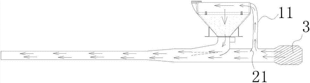
[0038] like figure 2 As shown, a powder-displacing fire extinguisher includes a powder box 1, a gun barrel 2 and a main pressure source 3, and the main pressure source 3 is a ducted fan. The main pressure source 3 pressurizes the gun barrel 2 from the breech of the gun barrel 2, and the powder filling box 1 is fixed on the outer peripheral surface of the gun barrel 2;

[0039] like figure 2 As shown, the powder filling box 1 includes an auxiliary pressurizing pipe 11, a box body 12, a flow control plate 13 and a steering gear 14, and the auxiliary pressurizing pipe 11 communicates with the top of the box body 12, as figure 2 As shown, the box body 12 is a bell mouth structure, and the connection end with the gun barrel 2 is a small diameter end. The box body 12 is communicated with the gun barrel 2, and the connection between the box body 12 and the gun barrel 2 is a confluence fork, and the confluence fork is provided with a backflow prevention plate 22, and the backflow...


PUM


Abstract

A powder drive type fire extinguishing cannon comprises a powder containing box, a cannon pipe and a main pressure source; the main pressure source pressurizes a cannon pipe from the cannon tail of the cannon pipe, the powder containing box is fixed to the peripheral face of the cannon pipe, the powder containing box comprises an auxiliary pressurizing pipe, a box body, a flow control plate and a steering engine, the auxiliary pressurizing pipe is communicated with the top of the box body, the box body is communicated with the cannon pipe, the connecting position of the box body and the cannon pipe is a flow combining fork, the flow control plate partitions a channel for communicating the box body with the cannon pipe, and the steering engine controls the flow control plate. Powder fire extinguishing agents can be continuously sprayed out, and the beneficial effects of being small in recoil and small in weight are achieved.

Description

technical field [0001] The invention relates to the field of fire extinguishing guns, in particular to a powder driving type fire extinguishing gun. Background technique [0002] Due to the limited lifting height of existing fire trucks, there is no effective way to extinguish high-rise fires. Therefore, many manufacturers are thinking of launching fire extinguishing bombs from the ground or drones to extinguish the fire, but because the launcher has requirements for the weight of the fire extinguishing bombs , so the dry powder limit of the warhead belt is limited, and the warhead does not necessarily explode around the fire point when it enters the house. At the same time, the shrapnel produced by the explosion of the warhead is extremely easy to cause injury to personnel. Contents of the invention [0003] Aiming at the deficiencies in the prior art, the present invention proposes a powder-displacing fire extinguishing cannon, which realizes the continuous spraying of t...

Claims


Application Information

Patent Timeline
Patent Type & Authority Applications(China)
IPC IPC(8): A62C31/00A62C31/28
CPCA62C31/00A62C31/28A62C99/0045
Inventor 曹兵
Owner 重庆国飞通用航空设备制造有限公司
Why Eureka
Try Eureka