Fluid channel, motor with same and solid-liquid separation system
A fluid channel and motor shaft technology, applied in the field of centrifuges, can solve the problems that cannot fully meet the needs of solid-liquid mixture separation, equipment cleaning verification is difficult, noise and vibration are large, etc., to achieve smooth channels, simple equipment manufacturing and installation, Avoid vibration and noise effects
- Summary
- Abstract
- Description
- Claims
- Application Information
AI Technical Summary
Problems solved by technology
Method used
Image

Examples
Embodiment 1
[0065] This embodiment is a motor stator with a static part of the fluid channel, and the attached Figure 4 The static part of the fluid channel.
[0066] The integrally molded fluid channel stationary part includes: a cylindrical motor housing (409) and a yoke positioning protrusion (401) located inside the housing for positioning the stator unit; an outer ring (404) and the inner ring (406) form a bottomed annular cavity, the annular cavity and the pipeline (405) at the bottom of the annular cavity constitute the static part (407) of the fluid channel; the inner ring of the annular cavity is a bearing chamber The motor shaft mounting hole (408), the outer ring of the annular cavity extending outwards for connecting the motor casing has a ventilation hole (403) and a positioning through hole (402).
[0067] Insert the stator unit into the motor casing, and the injection-molded motor stator with fluid channel static part is roughly as attached Figure 5 As shown, the top ha...
Embodiment 2
[0069] This embodiment is a motor stator with a static part of the fluid channel, and the attached Figure 8 The static part of the fluid channel.
[0070] The integrally molded fluid channel static part includes: a bottomed annular cavity formed by an outer ring and an inner ring, and a fluid channel static part ( 407); the inner side of the inner ring of the annular cavity is a motor shaft mounting hole (408) with a bearing chamber, and the outer ring of the annular cavity extends outwards to fix the electronic unit with ventilation holes (403) and stator unit positioning holes (801 ).
[0071] After the stator unit is fixed in the positioning hole (801) of the stator unit by fixing screws or other methods, the injection molded motor stator with a static part of the fluid channel is roughly as attached Figure 5 As shown, the top has a liquid blocking boss (503) to prevent liquid from flowing in, and the bottom has a base (501) to increase the contact surface.
Embodiment 3
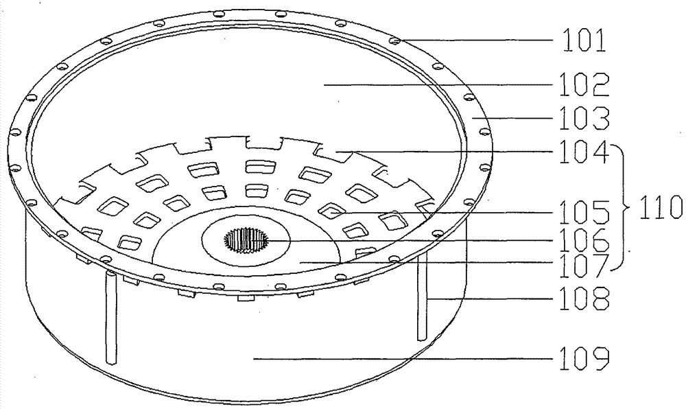
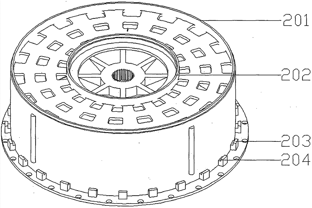
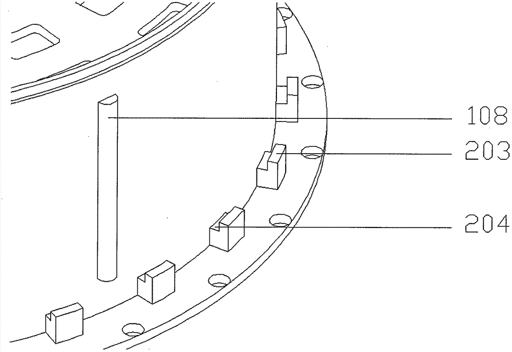
[0073] This embodiment is a motor rotor with a fluid channel rotating part, using the attached figure 1 , 2 , 3 fluid channel rotating part.
[0074] The integrally molded fluid channel rotating part includes: a guide ring surrounded by an outer ring (201) and an inner ring (202); a circular spacer plate ( 110), the center of the circular spacer plate is a conical boss (107) with a motor shaft mounting hole (106), and at least one circle with the motor shaft as the centerline includes an inner edge through hole (105) and an outer edge through hole The liquid outflow channel of (104) is positioned on the circular spacer plate between the conical boss (107) and the bottom of the liquid collection cavity inner wall (102); The radius of the edge is greater than the radius of the outer edge of the liquid blocking boss (503) on the top of the motor stator to prevent liquid from flowing in, and the end surface (103) has a positioning hole (101). The outer wall (109) of the liquid...
PUM
 Abstract
Description
Claims
Application Information
 - Generate Ideas
- Intellectual Property
- Life Sciences
- Materials
- Tech Scout
- Unparalleled Data Quality
- Higher Quality Content
- 60% Fewer Hallucinations
Browse by: Latest US Patents, China's latest patents, Technical Efficacy Thesaurus, Application Domain, Technology Topic, Popular Technical Reports.
© 2025 PatSnap. All rights reserved.Legal|Privacy policy|Modern Slavery Act Transparency Statement|Sitemap|About US| Contact US: help@patsnap.com