Improved rotary ice feeding system and operating method thereof

An ice-feeding and ice-feeding technology, which is applied to rotary conveyors, conveyors, transportation and packaging, etc., can solve problems such as affecting the efficiency of ice body transportation, the quality of ice output, reducing economic benefits, and affecting the strength of wind pressure, etc. Achieve the effect of improving conveying efficiency and conveying quality, eliminating material accumulation, and ensuring smooth feeding

Inactive Publication Date: 2017-09-15
HAINING WENSHUO TECH CONSULTING CO LTD
View PDF6 Cites 2 Cited by
  • Summary
  • Abstract
  • Description
  • Claims
  • Application Information

AI Technical Summary

Problems solved by technology

[0004] In the prior art, rotary conveying equipment is usually used to convey powder materials, but it is impossible to convey solid block materials, especially ice solid blocks
Due to the characteristics of ice, in the steering conveying cavity of the rotary conveying equipment, it will often adhere to the inner wall of the cavity, and because of the air leakage structure of the equipment, it will affect the wind pressure intensity, resulting in the ice sticking to the inner wall cannot be timely It is transmitted out, and the amount of ice entering the next time is still measured, so excess ice will accumulate in the cavity with a fixed volume, which will eventually lead to abnormal operation and a mechanical lock state
Due to this problem, the normal ice delivery operation cannot be realized, which affects the ice delivery efficiency and ice quality, and also causes equipment damage, increases production costs, and reduces economic benefits. It is basically not advisable in actual ice delivery operations.

Method used


Image

  • Improved rotary ice feeding system and operating method thereof
  • Improved rotary ice feeding system and operating method thereof
  • Improved rotary ice feeding system and operating method thereof

Examples


Embodiment Construction

[0025] The following are specific embodiments of the present invention and in conjunction with the accompanying drawings, the technical solutions of the present invention are further described, but the present invention is not limited to these embodiments.

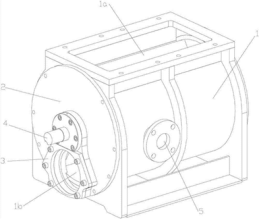
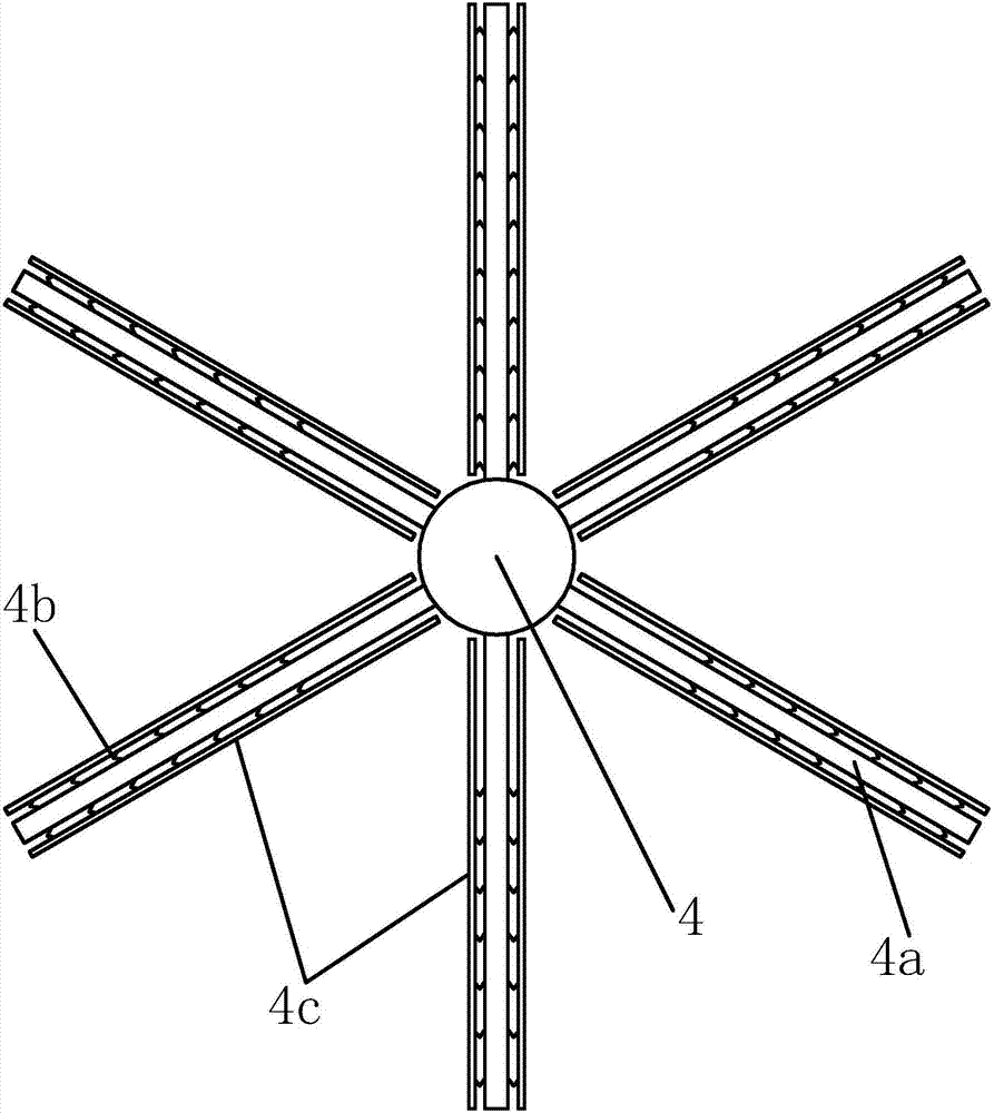
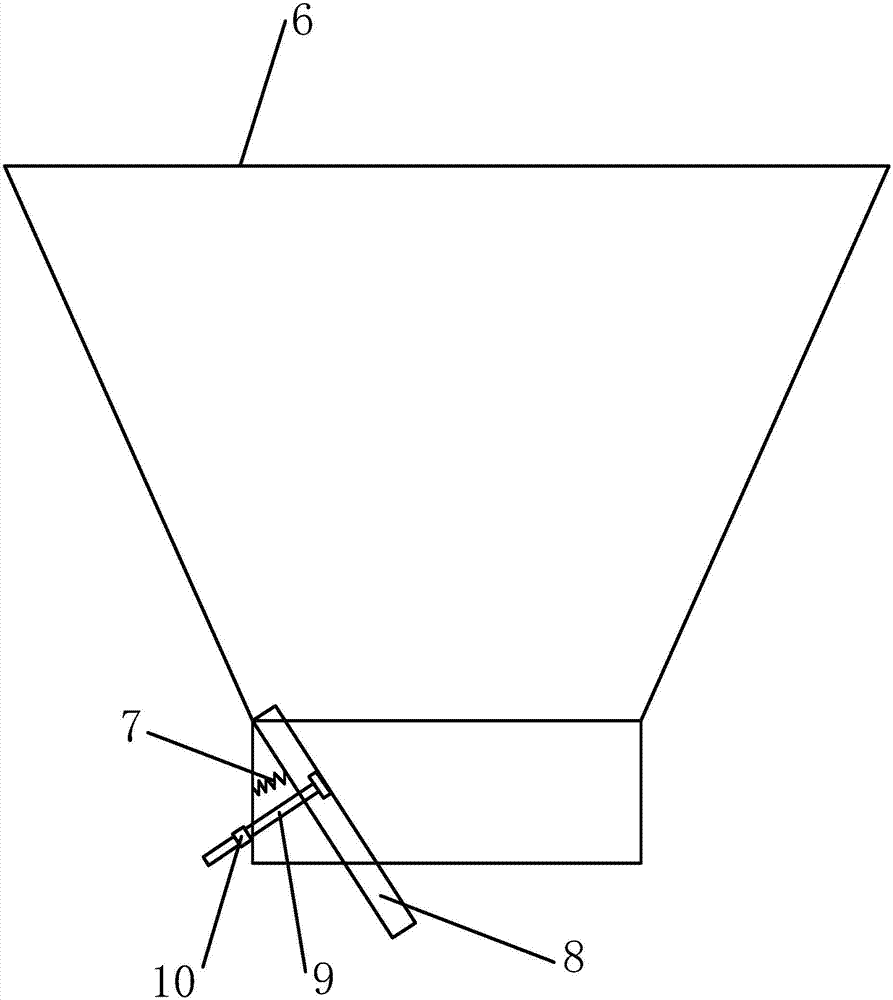
[0026] like figure 1 , figure 2 and image 3 As shown, the improved rotary ice delivery system includes an ice hopper 6, a rotary ice supplier, a blower, and an ice delivery pipeline. The rotary ice supplier includes a cylindrical casing 1, and the top of the casing 1 is provided with a discharge opening 1a. , the two ends of the casing 1 open the ice delivery port, the discharge port of the ice hopper 6 is located directly above the discharge port 1a, the blower is sealed and connected to the ice delivery port at one end of the casing 1, and the ice delivery pipe is sealed and connected to the casing 1 At the other end of the ice delivery port, a material guide plate 8 is provided at the outlet of the ice hopper 6, the...


PUM


Abstract

The invention provides an improved rotary ice delivery system and its operation method. The improved rotary ice delivery system includes an ice hopper, a rotary ice delivery device, a blower and an ice delivery pipeline. A material guide plate is arranged at the outlet of the ice hopper, and the top of the material guide plate is hinged on the inner wall of the ice hopper. , a support spring is set between the material guide plate and the inner wall of the ice hopper, and a bolt adjustment assembly is also set between the material guide plate and the inner wall of the ice hopper, and the rotating blade shaft rotates along the axis in the casing, and the rotating blade shaft is radial A number of vanes are evenly distributed, and a trapezoidal cavity is formed between each adjacent two vanes. The trapezoidal cavity between each adjacent two vanes is turned to the upper side to connect with the discharge port. The trapezoidal cavity in the middle turns to the bottom to connect with the ice delivery ports at both ends, and forms a circumferential airtight ice delivery channel. The vibrating plates are set on the two side walls of the vane plate, and a spring layer is set between the vane plate and the vibrating plate. The spring layer It consists of several evenly distributed soft springs.

Description

technical field [0001] The invention belongs to the technical field of refrigerating equipment, and relates to a device for transporting ice by turning and sealing the direction of wind, in particular to an improved rotary ice delivery system and its operation method. Background technique [0002] With the development of society and the continuous improvement of people's production level, the industries that use ice are becoming more and more extensive, and the quality requirements for ice are getting higher and higher. Therefore, the requirements for "high performance", "low failure rate", "hygiene", "production quality and efficiency" of ice industry equipment are becoming more and more urgent. Ice industry equipment has been widely used in industries and commerce such as aquatic products, food, supermarkets, dairy products, medicine, chemistry, vegetable preservation and transportation, and marine fishing. [0003] In the ice-making industry, all aspects of ice productio...

Claims


Application Information

Patent Timeline
IPC IPC(8): B65G29/00B65D88/70
CPCB65G29/00B65D88/703
Inventor 林晓丽陈晔
Owner HAINING WENSHUO TECH CONSULTING CO LTD
Why Eureka
Try Eureka