Weaving framework for conveying belt

A conveyor belt and skeleton technology, applied in textile, fabric, textile and papermaking, etc., can solve the problems of long joint time, loss of strength, and thick core thickness.

Inactive Publication Date: 2017-09-15
YANKUANG DONGHUA HEAVY IND CO LTD +1
View PDF5 Cites 1 Cited by
  • Summary
  • Abstract
  • Description
  • Claims
  • Application Information

AI Technical Summary

Problems solved by technology

Conveyor belts are widely used in cement, coking, metallurgy, chemical industry, steel and other industries where the conveying distance is short and the conveying volume is small. It affects the service life of the conveyor belt and whether the conveyor line can run smoothly. The common methods of conveyor belt joints mainly include mechanical joints and thermal vulcanized joints. Among them, mechanical joints generally refer to joints using belt buckles. This joint method is convenient and convenient. It is more economical, but the efficiency of joints is low and easy to be damaged, which has a certain impact on the service life of conveyor belt products, especially those with low strength; heat vulcanized joints are an ideal joint method, which can ensure high joint quality. Efficiency, but also relatively stable, the joint life is also very long, easy to master, but there are disadvantages such as troublesome process, high cost, long joint time, etc.
[0003] At present, the main material of the belt core s...

Method used


Image

  • Weaving framework for conveying belt

Examples


Embodiment Construction

[0026] The invention provides a braided skeleton for a conveyor belt and a conveyor belt to achieve the purpose of reducing the thickness of the belt core while ensuring the strength of the mechanical structure, facilitating splicing, and reducing splicing costs and time.

[0027] The following will clearly and completely describe the technical solutions in the embodiments of the present invention with reference to the accompanying drawings in the embodiments of the present invention. Obviously, the described embodiments are only some, not all, embodiments of the present invention. Based on the embodiments of the present invention, all other embodiments obtained by persons of ordinary skill in the art without making creative efforts belong to the protection scope of the present invention.

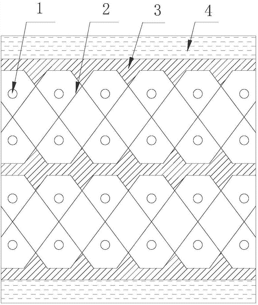
[0028] see figure 1 , figure 1 It is a schematic structural diagram of the braided skeleton for the conveyor belt provided by the embodiment of the present invention.

[0029] The woven s...


PUM

PropertyMeasurementUnit
Thicknessaaaaaaaaaa
Thicknessaaaaaaaaaa

Abstract

The invention discloses a weaving framework for a conveying belt. The weaving framework comprises warp threads and weft threads, wherein the weft threads include upper-layer weft threads and lower-layer weft threads, the strand number of the warp threads is four, two strands of warp threads are alternatively woven with an uneven number of weft threads in the lower-layer weft threads and an even number of weft threads in the upper-layer weft threads in an opposite-direction mode, the other two strands of warp threads are alternatively woven with an uneven number of weft threads in the lower-layer weft threads and an even number of weft threads in the upper-layer weft threads in an opposite-direction mode, and two strands of warp threads are mutually staggered with the other two strands of warp threads to form a network. Compared with a framework structure in the prior art, the weaving framework for the conveying belt is higher in structural structure strength, the conveying belt including the framework can be connected by using the mode of a mechanical joint, is economic, convenient and quick, repeated calendaring and rubberizing in the conveying belt manufacturing process are not needed, the thickness of the conveying belt can be remarkably decreased, and the phenomenon that the conveying belt produces interlaminar glue failure after the joint forms an annular shape is avoided. The invention also discloses the conveying belt.

Description

technical field [0001] The invention relates to the technical field of conveyor belts, in particular to a braided framework for a conveyor belt and a conveyor belt. Background technique [0002] Conveyor belt is a rubber and fiber, metal composite product, or plastic and fabric composite product that carries and transports materials. Conveyor belts are widely used in cement, coking, metallurgy, chemical industry, steel and other industries where the conveying distance is short and the conveying volume is small. It affects the service life of the conveyor belt and whether the conveyor line can run smoothly. The common methods of conveyor belt joints mainly include mechanical joints and thermal vulcanized joints. Among them, mechanical joints generally refer to joints using belt buckles. This joint method is convenient and convenient. It is more economical, but the efficiency of joints is low and easy to be damaged, which has a certain impact on the service life of conveyor b...

Claims


Application Information

Patent Timeline
IPC IPC(8): D03D1/00D03D13/00D03D15/00D06N3/00
CPCD03D1/0094D03D13/00D03D15/00D06N3/0006D06N3/0034D06N3/0036D10B2331/02D10B2331/04
Inventor 黄孝庭汪光亮孙桂美杨静吴旗高峰李兴强李振亮刘孟芸庞志安
Owner YANKUANG DONGHUA HEAVY IND CO LTD
Why Eureka
Try Eureka