Supercharge Your Innovation With Domain-Expert AI Agents!

Multi-stage beating device for textile fibers

A textile fiber and power device technology, which is applied in the field of textile fiber multi-stage beating devices, can solve the problems of incomplete beating of pulp and difficulty in beating pulp fully, so as to avoid thorough beating, improve the crushing effect, and improve the chopping effect Effect

Inactive Publication Date: 2017-09-15
CHANGXING COUNTY DAWEI TEXTILE CO LTD
View PDF1 Cites 0 Cited by
  • Summary
  • Abstract
  • Description
  • Claims
  • Application Information

AI Technical Summary

Problems solved by technology

[0004] The purpose of the present invention is to address the deficiencies of the prior art, and to overcome the incomplete beating of the slurry and the edge of the slurry bucket by setting the two-stage beating device to perform multi-stage beating on the slurry and setting the slurry bucket to swing left and right. Part of the slurry is difficult to fully beat the problem

Method used


Image

  • Multi-stage beating device for textile fibers
  • Multi-stage beating device for textile fibers
  • Multi-stage beating device for textile fibers

Examples


Embodiment 1

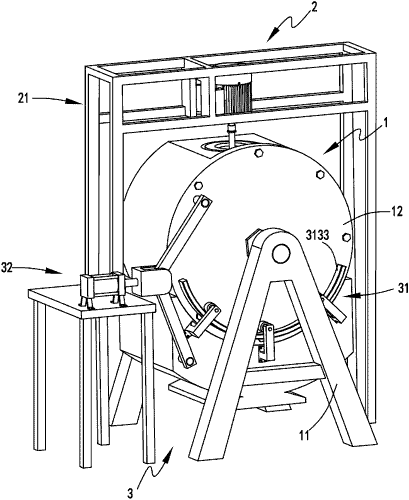
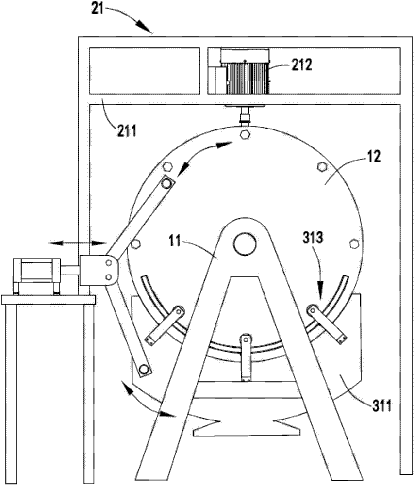
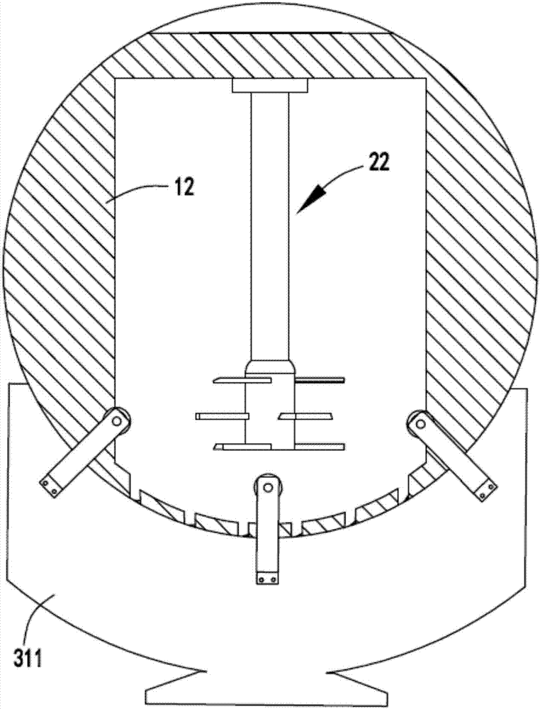
[0034] figure 1 It is a schematic diagram of the structure of the secondary beating equipment, figure 2 It is a schematic diagram of the front view of the secondary beating equipment, image 3 It is a cutaway diagram of the slurry tank, Figure 4 It is a cut-away schematic diagram of the secondary beating part, Figure 5 It is an enlarged schematic diagram of the relative position of cutter a and cutter b, Image 6 It is a schematic diagram of the structure of the rotating discharge member and the driving mechanism, Figure 7 It is a schematic diagram of the structure of the first-stage beating device. like figure 1 , figure 2 , image 3 , Figure 4 , Figure 5 , Image 6 and Figure 7 As shown, a textile fiber multistage beating device includes a main body 1, the main body 1 includes a support frame 11 and a slurry barrel 12 rotatably arranged on the support frame 11 for placing pulp to be beaten;

[0035] A first-stage beating part 2, the first-stage beating pa...

Embodiment 2

[0052] like figure 1 , figure 2 , image 3 , Figure 4 , Figure 5 , Image 6 and Figure 7 As shown, the components that are the same as or corresponding to those in the first embodiment are marked with the corresponding reference numerals in the first embodiment. For the sake of simplicity, only the differences from the first embodiment will be described below. The difference between the second embodiment and the first embodiment is that: further, the rotating support device 313 includes a turret 3131 fixedly arranged on both sides of the rotating discharge member 311, and rollers rotatably arranged on the turret 3131 3132 and arc-shaped support rails 3133 arranged on both sides of the slurry bucket 12, the rollers 3132 roll along the arc-shaped support rails 3133;

[0053] By setting the track 3133, the roller 3132 can rotate directionally, and the track 3133 is set along the circumferential trajectory of the slurry bucket 12, so that the trajectory of the rotating d...


PUM


Abstract

The invention relates to a multi-stage beating device for textile fibers. The multi-stage beating device comprises a body part, a first-stage beating part and a second-stage beating part, wherein the body part comprises a supporting frame and a pulp barrel, and the pulp barrel is rotationally arranged on the supporting frame and used for containing the to-be-beat pulp; the first-stage beating part comprises a power device and a first-stage beating device body, and the first-stage beating device body is driven by the power device to be used for beating the pulp in the pulp barrel; the second-stage beating part comprises a second-stage beating mechanism and a driving mechanism, the second-stage beating mechanism is arranged at the lower end of the pulp barrel, the driving mechanism is arranged on the same side of the pulp barrel and the second-stage beating mechanism, and the driving mechanism is used for driving the second-stage beating mechanism and the pulp barrel to rotate relatively so as to conduct secondary beating on the pulp flowing out from the bottom of the pulp barrel. By means of the multi-stage beating device, the problems that pulp beating is not thorough, and the pulp at the edge of the pulp barrel is difficult to beat sufficiently are solved.

Description

technical field [0001] The invention relates to the technical field of textile beating equipment, in particular to a multi-stage beating device for textile fibers. Background technique [0002] Sizing is a key process in weaving engineering. The purpose of sizing is to form a protective film on the yarn, improve the wear resistance of the yarn, reduce hairiness, increase the strength of the yarn appropriately, and reduce the elongation to withstand the yarn. The complex mechanical action ability in the weaving process improves the weaving performance of the yarn, and the slurry needs to be fully broken when producing mortar. [0003] A Chinese utility model patent with the authorized notification number CN205627773U discloses a high-efficiency beating machine for textile pulp, which can effectively and conveniently adjust the height of the stirring device by setting the screw and the bearing to work together. At the same time, the servo motor and the The asynchronous motor ...

Claims


Application Information

Patent Timeline
Patent Type & Authority Applications(China)
IPC IPC(8): D06B23/20B02C18/04B02C18/02
CPCD06B23/205B02C18/02B02C18/04
Inventor 臧伟
Owner CHANGXING COUNTY DAWEI TEXTILE CO LTD
Features
  • R&D
  • Intellectual Property
  • Life Sciences
  • Materials
  • Tech Scout
  • Unparalleled Data Quality
  • Higher Quality Content
  • 60% Fewer Hallucinations
Learn More