Installation method of no-bracket prefabricated bracket intermediate beam

An installation method and corbel technology, applied in bridges, bridge materials, bridge construction, etc., can solve problems such as unfavorable operation management, poor corbel design, harmful secondary stress, etc.

Active Publication Date: 2017-09-15
CHINA FIRST METALLURGICAL GROUP
View PDF5 Cites 3 Cited by
  • Summary
  • Abstract
  • Description
  • Claims
  • Application Information

AI Technical Summary

Problems solved by technology

Due to the reduction of the section height of the positive and negative corbels, the shear force is also reduced, which can only be compensated by the local steel content. Therefore, a large number of steel bars are added to the positive and negative corbels to solve the shear force problem of the beam. Local reinforcements are densely distributed, which also has a great impact on construct

Method used


Image

  • Installation method of no-bracket prefabricated bracket intermediate beam
  • Installation method of no-bracket prefabricated bracket intermediate beam
  • Installation method of no-bracket prefabricated bracket intermediate beam

Examples


Embodiment 1

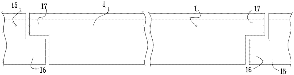
[0029] Such as Figure 2 to Figure 5 As shown, taking a 40m box girder of a certain bridge as an example, the girder weighs about 120t and is installed between fixed beams 15 at both ends. The box girder is designed without corbels.

[0030] The weight of the beam at one end of the box girder is 60t, and 8 reinforced I 56 Word steel. The construction design calculates the reserved holes for the suspender 9 to pass under the prefabricated joist beam 1, and the reserved holes for installing the cross arm 10 on both sides of the bottom of the prefabricated joist beam 1;

[0031] A method for installing prefabricated joist beams without corbels, comprising the following steps:

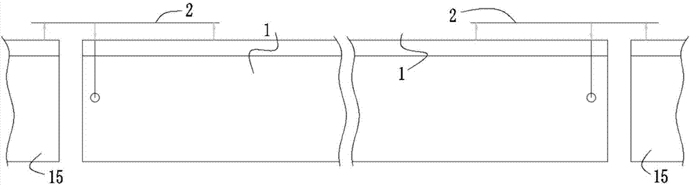
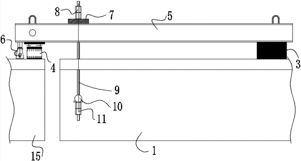
[0032] Step 1. First install the reverse beam hanger 2 at both ends of the prefabricated bracket beam 1 respectively. The reverse beam hanger 2 includes two boom assemblies, support pads 3, and a horizontal bar 5 made of I-shaped steel. , the crossbar 5 is arranged above the prefabricated bay beam 1, th...

Embodiment 2

[0040] Such as Figure 5 and Figure 6 As shown, the difference between Embodiment 2 and Embodiment 1 is that the prefabricated joist beam 1 is a T-shaped beam, and each end of the T-shaped beam is connected with four crossbars 5 through a set of suspender assemblies, and the crossarm 10 is directly Located at the bottom of the T-beam, the cross arm 10 is connected to the four cross-bars 5 above the T-beam through two suspenders 9. Compared with Example 1, Implementation 2 lacks a set of suspender components. The bottom of the joist beam 1 does not need to be provided with a reserved hole for the cross arm 10, and the others are the same as in the first embodiment.

[0041] The cross bar 5 that adopts in above-mentioned embodiment 1 and embodiment 2 is I-shaped steel, specifically I 56 Word steel, the suspender 9 adopts finish-rolled rebar, and the specific dimensions of the cross bar 5 and the suspender 9 are calculated and designed according to the weight and size of the p...


PUM


Abstract

The invention discloses an installation method of a no-bracket prefabricated bracket intermediate beam. The method of the no-bracket prefabricated bracket intermediate beam comprises the following steps that two ends of the prefabricated bracket intermediate beam are provided with reverse balance arm hanging frames correspondingly first, and each reverse balance arm hanging frame comprises a suspender assembly, a support cushion block and a transverse rod made from I-shaped steel; the middle of each transverse rod is connected with the end part of the prefabricated bracket intermediate beam through the corresponding suspender assembly, one end of each transverse rod is supported on the prefabricated bracket intermediate beam through the corresponding support cushion block, and the other end of each transverse rod stretches out from the end part of the prefabricated bracket intermediate beam; then the prefabricated bracket intermediate beam is conveyed to the installation position through a bridge erecting machine; a jack is arranged on a fixed beam end and below each transverse rod, and the jack is used for adjusting elevation of the whole prefabricated bracket intermediate beam and fixed through a temporary cushion block; by adjusting the length of each suspender assembly, the level degree and the elevation of the whole prefabricated bracket intermediate beam are adjusted, and adjustment and position of the prefabricated bracket intermediate beam are completed after the adjustment is completed; and then welding, pouring and fixing are conducted on the prefabricated bracket intermediate beam. The installation method of the no-bracket prefabricated bracket intermediate beam is simple in structure, and the problem of the construction impact caused by installing the prefabricated beam by traditional brackets is reduced.

Description

technical field [0001] The invention belongs to the field of bridge construction, and relates to a method for installing a prefabricated beam, in particular to a method for installing a prefabricated joist beam without corbels. Background technique [0002] Designing continuous girder bridges is a commonly used method nowadays. There are many methods to solve the construction and installation of continuous girders. Setting positive and negative corbels at both ends of the prefabricated beams to be installed is a special design and construction method for previous construction. Due to the reduction of the section height of the positive and negative corbels, the shear force is also reduced, which can only be compensated by the local steel content. Therefore, a large number of steel bars are added to the positive and negative corbels to solve the shear force problem of the beam. The local reinforcements are densely distributed, which also has a great impact on the construction....

Claims


Application Information

Patent Timeline
IPC IPC(8): E01D21/00E01D101/28
CPCE01D21/00E01D2101/28
Inventor 王朋林郑金平肖祥郭继舟李少祥
Owner CHINA FIRST METALLURGICAL GROUP
Why Eureka
Try Eureka