
A micro-electromechanical two-axis gyroscope

A gyroscope and micro-electromechanical technology, applied in gyroscope/steering sensing equipment, gyro effect for speed measurement, instrument and other directions, can solve the problem of large output quadrature error, achieve the effect of reducing output error and improving output accuracy

Active Publication Date: 2022-04-05
SENODIA TECH (SHANGHAI) CO LTD
View PDF5 Cites 0 Cited by
  • Summary
  • Abstract
  • Description
  • Claims
  • Application Information

AI Technical Summary

Problems solved by technology

[0005] In view of this, the present invention provides a micro-electromechanical two-axis gyroscope to solve the problem that the output quadrature error is relatively large due to the large coupling between the driving mode and the detection mode of the MEMS gyroscope

Method used


Image

  • A micro-electromechanical two-axis gyroscope
  • A micro-electromechanical two-axis gyroscope

Examples


Embodiment Construction

[0027] Next, the technical solutions in the embodiments of the present invention will be described in connection with the drawings of the embodiments of the present invention, and it is understood that the described embodiments are merely the embodiments of the present invention, not all of the embodiments. Based on the embodiments of the present invention, all other embodiments obtained by those of ordinary skill in the art are in the range of the present invention without making creative labor premise.

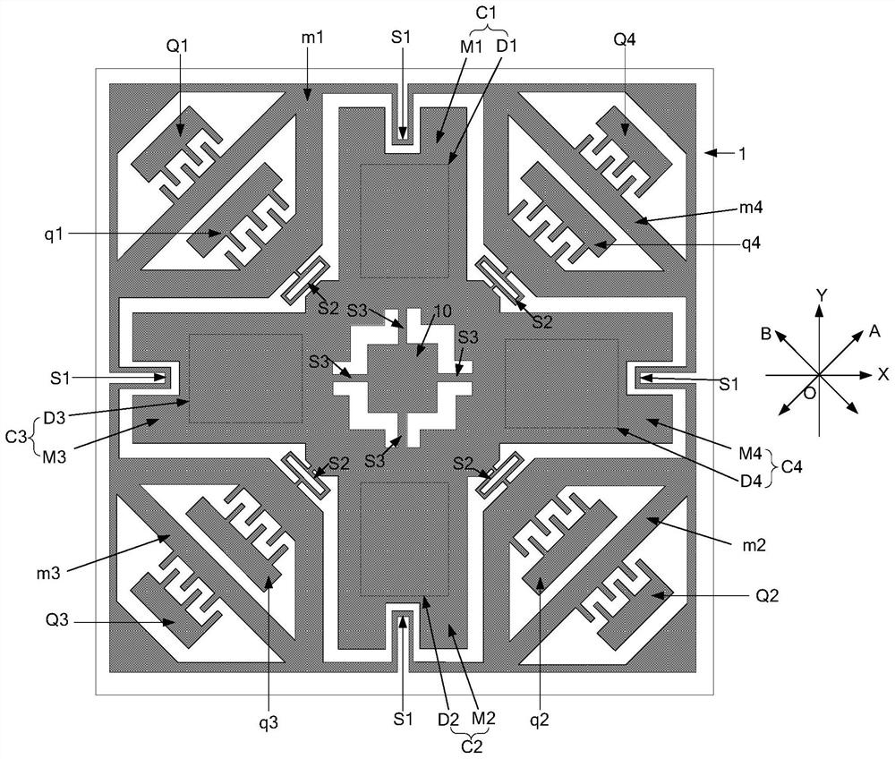
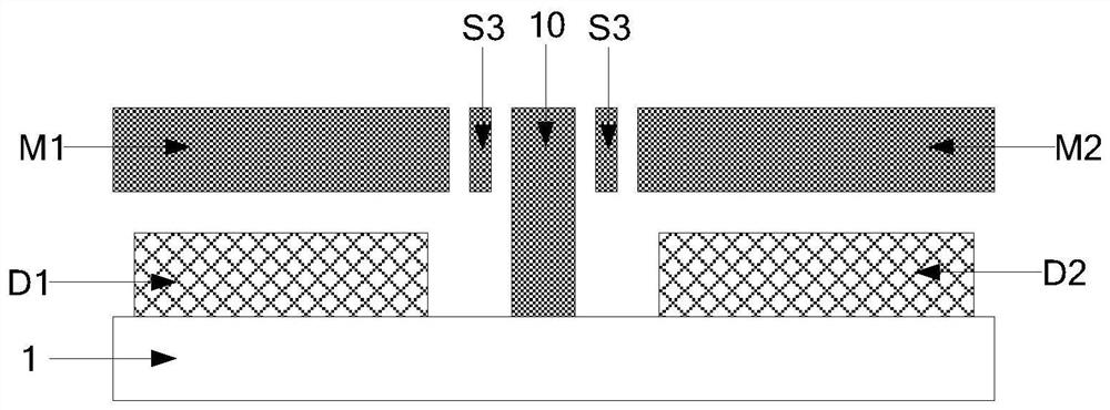
[0028] The embodiment of the present invention provides a two-axis gyroscope, such as figure 1 and figure 2 As shown, the two-axis gyroscope includes a substrate 1 and a mechanical structure disposed on the substrate 1 comprising two detection structures and a drive structure.

[0029] The drive structure includes at least two driving mass blocks and at least two drive electrodes, each of which constitutes a driving capacitor with an electric mass; the driving capacitor is used ...


PUM


Abstract

The invention provides a micro-electromechanical two-axis gyroscope, the driving structure includes a driving mass and a driving electrode, and the driving mass and the driving electrode constitute a driving capacitor; the driving capacitor is used to drive the driving mass to reciprocate in a specific direction Vibration; each detection structure includes a detection mass and a detection electrode, and the detection mass and the detection electrode constitute a detection capacitance; the detection capacitance is used to detect the Coriolis force generated on the drive mass to drive the detection mass around the first axis or the second axis Capacitance change due to motion. Since the direction of reciprocating vibration of the driving mass is different from the direction of motion of the detection mass, that is, the direction of movement around the first axis and the second axis, therefore, in the case of no angular velocity input, that is, no Coriolis force, the driving mass does not It will drive the movement of the detection mass, so that the mechanical decoupling of the driving structure and the detection structure in the driving mode can be realized, thereby reducing the output quadrature error of the gyroscope and improving the output accuracy of the gyroscope.

Description

Technical field [0001] The present invention relates to the field of microelectromechanical technologies, and more particularly to a microelectromechanical two-axis gyroscope. Background technique [0002] The MEMS gyroscope manufactured based on Micro Electro Mechanical System (MEMS), due to the small size, low cost, good integration, etc.,, therefore, it has been widely used in an important field of consumer electronics, medical, automobiles. [0003] The existing MEMS gyroscope has two working modality: drive modal and detection modalities. In the driving mode, the driving capacitor drive mass block is done to the composite vibration, that is, when the angular angle speed is subjected to the modal angle, the detection capacitance detection due to CHENCHC can change the capacitance change in the detection direction. To determine the angular velocity input to the MEMS gyroscope based on the capacitance change. [0004] However, since there is a large coupling between the driving...

Claims


Application Information

Patent Timeline
Patent Type & Authority Patents(China)
IPC IPC(8): G01C19/5712
CPCG01C19/5712
Inventor 邹波郭梅寒
Owner SENODIA TECH (SHANGHAI) CO LTD
Learn More