A Waveform Design Method Based on Cognitive Radar Anti-Multi-hop Clutter Interference

A technology of clutter interference and waveform design, applied to radio wave measurement systems, instruments, etc., can solve problems affecting the normal detection of targets, and achieve the effect of improving detection performance

Active Publication Date: 2020-05-19
HARBIN INST OF TECH
View PDF4 Cites 0 Cited by
  • Summary
  • Abstract
  • Description
  • Claims
  • Application Information

AI Technical Summary

Problems solved by technology

[0004] The purpose of the present invention is to solve the existing method to realize the separation of multi-hop clutter and target within a certain range while sacrificing part of the Doppler detection interval, because the size of the interval depends on the expansion width of multi-hop clutter, thus affecting the normal detection of the target In view of the shortcomings of detection, a design method based on cognitive radar anti-multi-hop clutter jamming waveform is proposed

Method used


Image

  • A Waveform Design Method Based on Cognitive Radar Anti-Multi-hop Clutter Interference
  • A Waveform Design Method Based on Cognitive Radar Anti-Multi-hop Clutter Interference
  • A Waveform Design Method Based on Cognitive Radar Anti-Multi-hop Clutter Interference

Examples


specific Embodiment approach 1

[0019] Specific implementation mode one: combine figure 1 , figure 2 To illustrate this embodiment, the specific process of a cognitive radar anti-multi-hop clutter interference waveform design method in this embodiment is as follows:

[0020] Step 1: The radar transmits the linear frequency modulation continuous wave signal outward, the receiver receives the echo signal, and the radar performs range Doppler two-dimensional processing on the echo signal to obtain the multi-hop clutter in the echo signal on the Doppler spectrum The width l of and the position f of the multi-hop clutter on the Doppler spectrum loction ;

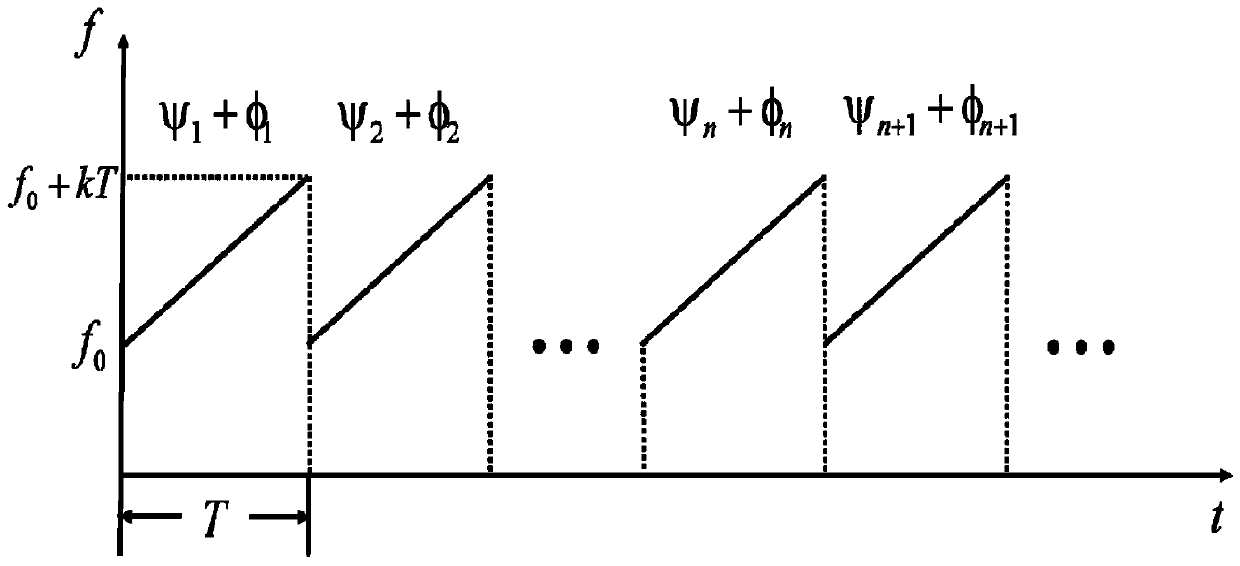
[0021] Step 2: Perform phase modulation on the basis of the linear frequency modulation continuous wave in step 1, and obtain the linear frequency modulation continuous wave signal waveform U after three phase modulations between pulses T (t); According to the width of the multi-hop clutter obtained in the step 1, obtain the phase encoding coefficient thre...

specific Embodiment approach 2

[0023] Specific embodiment 2: The difference between this embodiment and specific embodiment 1 is that in the step 1, the radar transmits a chirp continuous wave signal outwards, the receiver receives the echo signal, and the radar performs range Doppler on the echo signal. Two-dimensional processing to obtain the width l of the multi-hop clutter in the echo signal and the position f of the multi-hop clutter loction ; The specific process is:

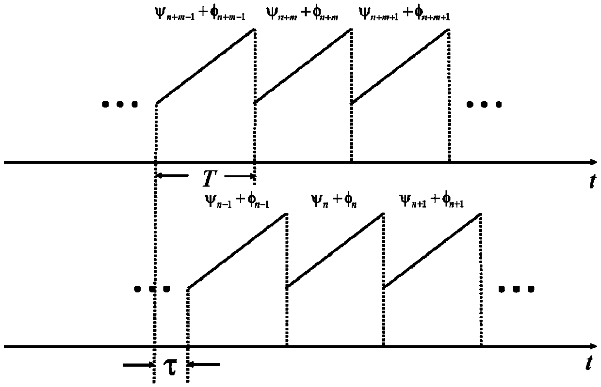
[0024] The radar transmits the linear frequency modulation continuous wave signal outwards, and the receiver performs range-Doppler two-dimensional processing on the echo to obtain the target range and velocity information; the multi-hop clutter enters the receiver through multiple reflections from the ionosphere. Inter-pulse is a non-linear change, so the multi-hop clutter will shift and broaden on the Doppler spectrum when performing inter-pulse Doppler processing.

[0025] Denote the ionospheric slow-path phase modulation function a...

specific Embodiment approach 3

[0038] Specific embodiment three: the difference between this embodiment and specific embodiment one or two is that: in the step two, phase modulation is performed on the basis of the linear frequency modulation continuous wave in step one, and the linear frequency modulation continuous wave after three phase modulations between pulses is obtained Signal waveform U T (t); According to the width of the multi-hop clutter obtained in step 1, three phase encoding coefficients are obtained to realize the compression of multi-hop clutter; the specific process is:

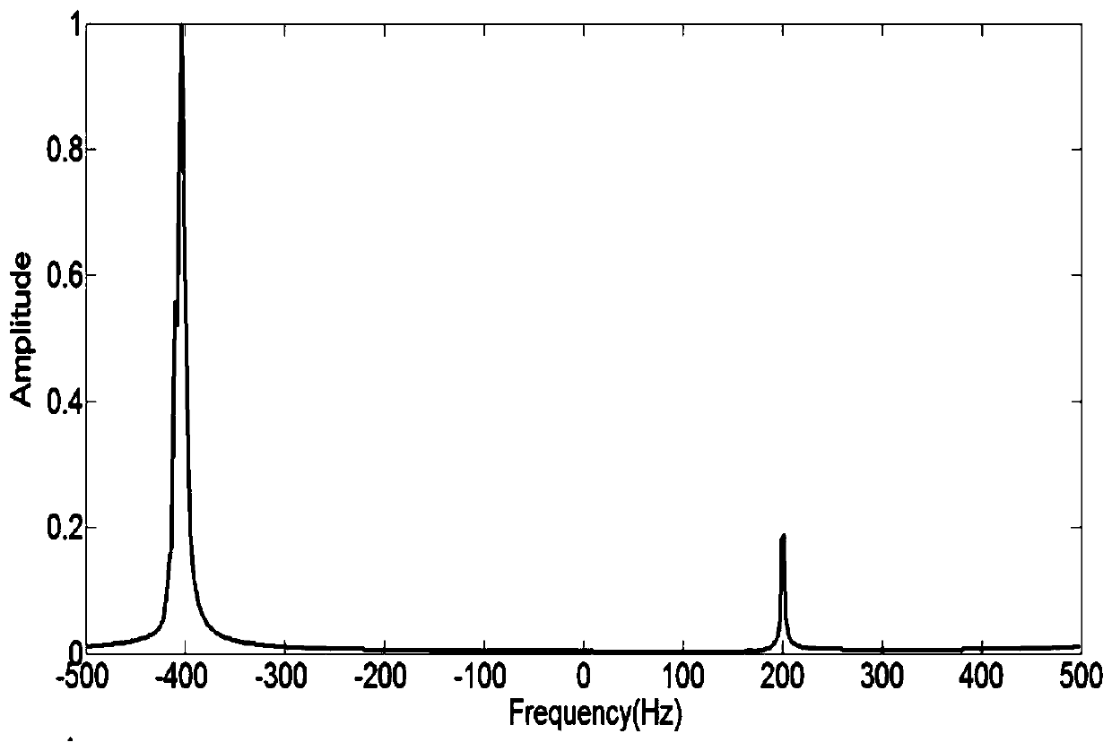
[0039] It has been known that the multi-hop clutter broadening is mainly produced by the quadratic term of the ionospheric slow phase path modulation function Taylor expansion; in order to compensate the quadratic term, the inter-pulse cubic phase encoding is performed on the basis of the original linear frequency modulation continuous wave , after the pulse pressure processing, there will be a linear variation and a quad...


PUM


Abstract

A cognitive radar-based anti-multi-hop clutter interference waveform design method, the invention relates to an anti-multi-hop clutter interference waveform design method. The purpose of the present invention is to solve the existing method to realize the separation of multi-hop clutter and target within a certain range, but at the same time sacrifice part of the Doppler detection interval, the size of the interval depends on the expansion width of multi-hop clutter, which affects the normal operation of the target. Detection of shortcomings. The process is as follows: 1: The radar emits a linear frequency modulation continuous wave signal, and the radar performs two-dimensional range Doppler processing on the echo signal to obtain the width and position of the multi-hop clutter in the echo signal on the Doppler spectrum ; Two: Phase modulation is performed on the basis of linear frequency modulation continuous wave, and U T (t); According to the width of the obtained multi-hop clutter, obtain the phase encoding coefficient three times, realize the compression of the multi-hop clutter; three: to U T (t) Carry out secondary phase encoding, so that the multi-hop clutter has a controllable shift on the Doppler spectrum. The invention is used in the technical field of radar anti-clutter.

Description

technical field [0001] The invention relates to a waveform design method for resisting multi-hop clutter interference. Background technique [0002] Doppler processing is a key step for high-frequency sky-wave over-the-horizon radar to achieve target detection. However, due to the multi-hop phenomenon in the transmission process of sky-wave radar, the multi-hop clutter beyond the coverage of radar power enters the receiver through multiple reflections between the ionosphere and the earth's surface to form Doppler spread clutter. Usually the echo energy of the target signal is much smaller than the energy of the multi-hop clutter. Therefore, when the Doppler frequency of the target is close to the Doppler frequency of the multi-hop clutter, the strong multi-hop clutter will appear in the Doppler spectrum overwhelm the target signal. Therefore, in order to ensure the normal detection and tracking of targets by sky-wave radar under the interference of multi-hop clutter, it ha...

Claims


Application Information

Patent Timeline
Patent Type & Authority Patents(China)
IPC IPC(8): G01S7/02
CPCG01S7/02G01S7/023
Inventor 位寅生张洋魏文艳于雷
Owner HARBIN INST OF TECH
Why Eureka
Try Eureka