A Calculation Method for Optimum Rotation Angular Velocity of Serving Spacecraft when Rotating at Fixed Axis

A technology for serving spacecraft and calculation methods, applied in the field of calculation of optimal rotation angular velocity, can solve problems such as three-axis tumbling motion, damage of docking mechanism, and difficulty in docking of tumbling targets, so as to save energy consumption and enhance safety , enhance the effect of stability

Active Publication Date: 2020-04-21
NORTHWESTERN POLYTECHNICAL UNIV
View PDF6 Cites 0 Cited by
  • Summary
  • Abstract
  • Description
  • Claims
  • Application Information

AI Technical Summary

Problems solved by technology

The docking of rolling targets is particularly difficult, because when the relative speed of the service spacecraft and the target is high, it is easy to cause collisions and damage the docking mechanism
For low-speed tumbling satellites, the movement of the space manipulator can be used to eliminate the relative angular velocity, but when the target angular velocity is too large, the movement of the manipulator alone often cannot meet the requirements
In the past, there was a method of reducing the relative angular velocity between the service spacecraft and the target rotating on a fixed axis by rotating the main body of the service spacecraft, but no research has proposed how to eliminate the relative velocity to the greatest extent for the target performing three-axis rolling motion

Method used


Image

  • A Calculation Method for Optimum Rotation Angular Velocity of Serving Spacecraft when Rotating at Fixed Axis
  • A Calculation Method for Optimum Rotation Angular Velocity of Serving Spacecraft when Rotating at Fixed Axis
  • A Calculation Method for Optimum Rotation Angular Velocity of Serving Spacecraft when Rotating at Fixed Axis

Examples


Embodiment Construction

[0034] The present invention will be further described below with reference to the accompanying drawings and embodiments.

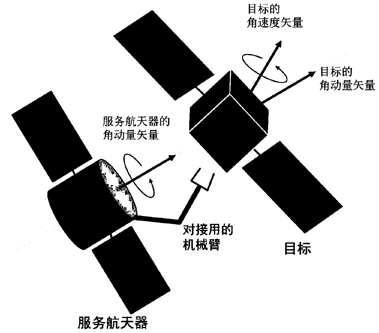
[0035] figure 1 is a schematic diagram of docking with a tumbling target using a rotating service spacecraft. As shown in the figure, since the service spacecraft rotates on a fixed axis, its angular momentum coincides with the direction of angular velocity and points to the direction of the target's angular momentum. Since the target is approximately considered not to be affected by the external moment, its angular momentum is conserved, and the direction of the angular momentum in the inertial coordinate system is fixed. At the same time, since the target performs arbitrary tumbling motion, its angular velocity vector does not necessarily coincide with the direction of angular momentum, and its orientation in the inertial coordinate system generally changes with time.

[0036] Through non-contact measurement methods, such as binocular vision method, l...


PUM


Abstract

The invention discloses a calculation method of optimal self-rotational angular velocity for fixed-axis rotation of a service spacecraft. The calculation method comprises steps of firstly carrying out Fourier transform on the measured gesture quaternion of an object to obtain three characteristic angular frequencies of object movement; using the filtering method to allow the estimation values of the angular frequencies to be quite accurate; and finally, multiplying the characteristic angular frequency with the biggest effect with 2 to obtain the optical angular velocity of the rotation of the service spacecraft. According to the invention, through the designed self-rotating angular velocity, the service spacecraft is allowed to rotate, so the relative angular velocity and the relative linear speed between the service spacecraft and the object can be effectively reduced, load during capturing of a mechanical arm is reduced and safety of on-orbit services in the space is improved; and in addition, although the service spacecraft carries out fixed-axis rotation, the designed self-rotating angular velocity is not only defined in objects carrying out fixed-axis rotation, so for objects rolling over along the three axes, the relative angular velocity can be also effectively reduced.

Description

Technical field: [0001] The invention relates to an on-orbit service technology in the aerospace field, in particular to a method for calculating the optimal rotation angular velocity when a service spacecraft rotates with a fixed axis. Background technique: [0002] At present, space on-orbit service technology is receiving widespread attention from researchers at home and abroad. Targets for in-orbit services in space include malfunctioning satellites and space debris. The purpose is to use a service spacecraft to repair the target or remove the target from its current orbit. One of the prerequisites for in-orbit service in space is the docking of the target. Since the external moment acting on the target in space is very small, the initial angular momentum of the target is difficult to dissipate, so it is often in a rolling state. The docking of the tumbling target is particularly difficult, because when the relative speed of the serving spacecraft and the target is la...

Claims


Application Information

Patent Timeline
Patent Type & Authority Patents(China)
IPC IPC(8): G05D1/08B64G1/64G06F17/14G06F17/16
CPCB64G1/244B64G1/64G06F17/141G06F17/16
Inventor 袁建平马川朱战霞袁源代洪华
Owner NORTHWESTERN POLYTECHNICAL UNIV
Why Eureka
Try Eureka