Automatic high-efficiency pesticide spray device

A pesticide spraying and high-efficiency technology, which is applied to the device for catching or killing insects, application, animal husbandry, etc., can solve the problems of crop growth impact, general spraying effect, and increased labor, so as to improve the uniformity of drug acceptance, Realize automatic stirring work and improve the effect of automatic control rate

Inactive Publication Date: 2017-09-19
付天龙
View PDF11 Cites 33 Cited by
  • Summary
  • Abstract
  • Description
  • Claims
  • Application Information

AI Technical Summary

Problems solved by technology

Although the manual method can spray the crops in all directions, it is labor-intensive and inefficient
At present, aircraft spraying and pesticide mechanical spraying can be used for machine tool spraying. Aircraft spraying requires a large planting area and high cost, so it is difficult to promote. In addition, traditional pesticide mechanical spraying adopts the method of spraying from top to bottom. When crops of different plant heights are often missed or not sprayed, the growth of crops that cannot be sprayed will be affected
At the same time, the existing crop spraying device has a low degree of automation, wastes manpower and material resources, increases the amount of labor, the spraying effect is average, and the labor efficiency is low.

Method used


Image

  • Automatic high-efficiency pesticide spray device
  • Automatic high-efficiency pesticide spray device
  • Automatic high-efficiency pesticide spray device

Examples


Embodiment Construction

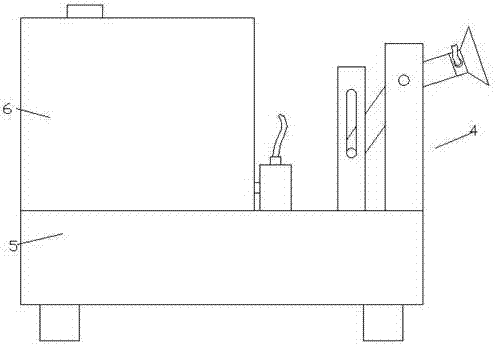
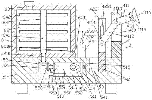
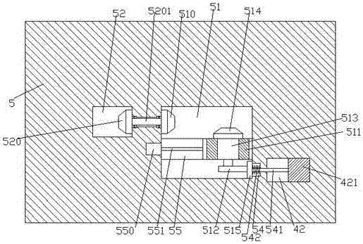
[0024] Such as Figure 1-Figure 5 As shown, an automatic and high-efficiency pesticide spraying device of the present invention includes a mobile vehicle body 5 and a spray box 6 arranged on the top left side of the mobile vehicle body 5, and a medicine storage cavity 62 is provided in the spray box 6 , The medicine storage cavity 62 is rotatably connected with a stirring mechanism 64, the mobile vehicle body 5 at the bottom of the spray box 6 is provided with a first transmission cavity 52, and the first transmission cavity 52 is located on the right side of the first transmission cavity 52. The mobile vehicle body 5 is provided with a second transmission cavity 51 extending to the front side, and on the right side of the front extension section of the second transmission cavity 51, the mobile vehicle body 5 is provided with a top that penetrates the mobile vehicle body 5 The guide groove 53 on the top end surface, the wall of the mobile vehicle body 5 between the first transm...


PUM


Abstract

The invention discloses an automatic high-efficiency pesticide spray device. The device comprises a mobile frame, and a spray tank arranged on the top of the left side of the mobile frame, wherein a pesticide storage cavity is formed in the spray tank, and a stirring mechanism is connected in the pesticide storage cavity in a matched connection manner; a first transmission cavity is formed in the mobile frame at the bottom of the pesticide spray tank; a second transmission cavity is formed in the mobile frame on the right side of the first transmission cavity and extends forward; a guide groove is formed in the mobile frame on the right side of the front extending section of the second transmission cavity, and the top of the guide groove runs through the end face of the top part of the mobile frame; a first rotating shaft is connected into the wall body of the mobile frame between the first transmission cavity and the second transmission cavity in a matched connection manner, and extends toward left and right sides; the left end of the first rotating shaft extends into the first transmission cavity, and a first bevel gear is fixedly arranged at the tail end of the left end of the first rotating shaft; and the right extending section of the first rotating shaft extends into the first transmission cavity, and a second bevel gear is fixedly arranged at the tail end of the right extending section of the first rotating shaft. The automatic high-efficiency pesticide spray device has a simple structure, and can meet the requirement of uniformly spraying crops having different plant heights, so that the spraying efficiency can be improved, and automatic stirring operation can be realized.

Description

Technical field [0001] The invention relates to a pesticide spraying device, which is an automatic and efficient pesticide spraying device. Background technique [0002] During the growing process of crops, they will inevitably be attacked by pests and diseases. Spraying pesticides is a common method to prevent pests and diseases. During the growth process of crops, they are more affected by pests and diseases. According to the growth cycle, they need to be sprayed regularly. At present, there are two main spraying methods, one is manual method, and the other is machine spraying. Although manual methods can spray all crops, they are labor intensive and low in efficiency. Aircraft spraying and pesticide mechanical spraying are currently available for machine tool spraying. Aircraft spraying requires a large planting area and high cost of use, so it is difficult to promote. In addition, traditional pesticide mechanical spraying is sprayed from top to bottom. Crops of different pl...

Claims


Application Information

Patent Timeline
Patent Type & Authority Applications(China)
IPC IPC(8): A01M7/00
CPCA01M7/0042A01M7/005A01M7/0089
Inventor 付天龙
Owner 付天龙
Why Eureka
Try Eureka