Spine fixing assembly

A technology for fixing components and spine, applied in the field of spinal fixation components, can solve the problem of lack of bone barrier protection in the spinal dura mater, and achieve the effect of avoiding the adhesion between the dural sac and nerve roots and relieving pain

Pending Publication Date: 2017-09-19
BEIJING AKEC MEDICAL
View PDF10 Cites 7 Cited by
  • Summary
  • Abstract
  • Description
  • Claims
  • Application Information

AI Technical Summary

Problems solved by technology

[0003] The main purpose of the present invention is to provide a spinal fixation assembly to solve the problem in the prior art that the spinal dura mater at the corresponding position lacks bone barrier protection after partial resection or overall removal of the vertebral body

Method used


Image

  • Spine fixing assembly
  • Spine fixing assembly
  • Spine fixing assembly

Examples


Embodiment 1

[0075] The design steps and manufacturing method of the spinal fixation assembly of Embodiment 1 are as follows:

[0076] 1. First, use the interactive medical image control system to establish the vertebral body segment (affected vertebral body) and the adjacent healthy physiological vertebral body segment of the patient's spinal disease based on the patient's CT or MRI and other medical three-dimensional tomographic scan data. 3D model;

[0077] 2. According to the plan formulated by the medical diagnosis, the part that is expected to be resected is removed from the three-dimensional model;

[0078] 3. Design spinal fixation components according to the need to fill the space of the occupied bone defect;

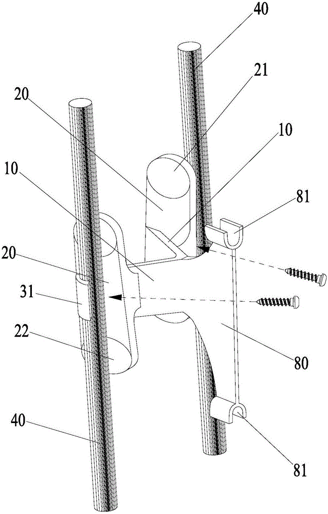
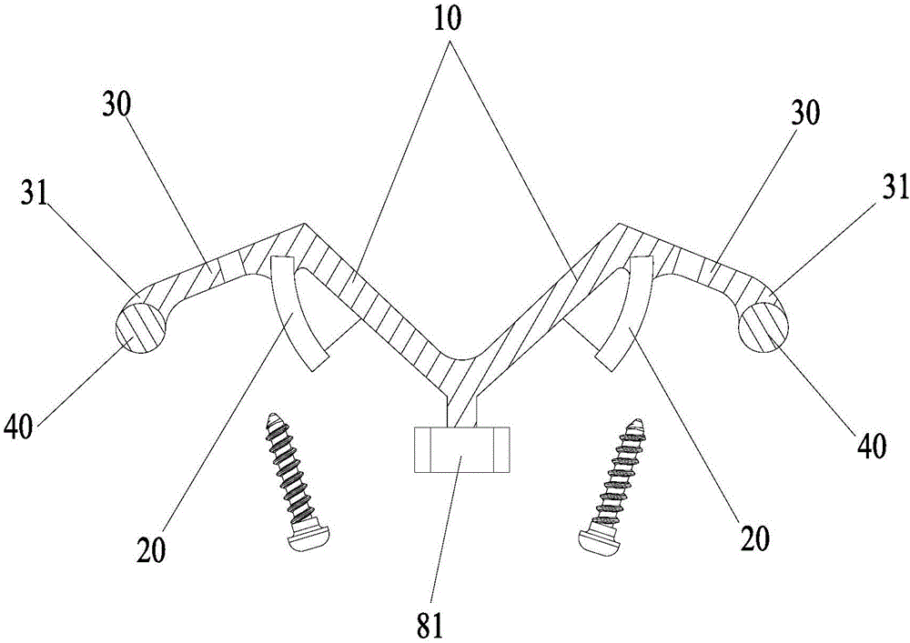
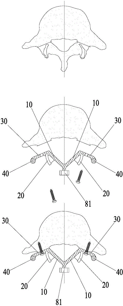
[0079] 4. When designing the spinal canal covering plate 10, enough space for the spinal canal should be reserved;

[0080] 5. The designed upper spinous process junction 81 should be in good contact with the lower edge of the spinous process of the upper adjacent healthy...

Embodiment 5

[0090] The design steps and manufacturing method of the spinal fixation assembly of Embodiment 5 are as follows:

[0091] 1. First, use the interactive medical image control system to establish a three-dimensional model of the affected vertebral body of the patient's spine and the adjacent healthy physiological vertebral body segments based on the patient's CT or MRI and other medical three-dimensional tomographic scanning data;

[0092] 2. According to the plan formulated by the medical diagnosis, the part that is expected to be resected is removed from the three-dimensional model;

[0093] 3. Design spinal fixation components according to the need to fill the space of the occupied bone defect;

[0094] 4. When designing the spinal canal covering plate 10, enough space for accommodating the spinal canal should be reserved;

[0095] 5. The designed first articular process junction should have good contact fit or fit with the inferior articular process of the upper adjacent he...

Embodiment 6

[0101] The design steps and manufacturing method of the spinal fixation assembly of Embodiment 6 are as follows:

[0102] 1. First, use the interactive medical image control system to establish a three-dimensional model of the affected vertebral body of the patient's spine and the adjacent healthy physiological vertebral body segments based on the patient's CT or MRI and other medical three-dimensional tomographic scan data;

[0103] 2. According to the plan formulated by the medical diagnosis, the part that is expected to be resected is removed from the three-dimensional model;

[0104] 3. Design spinal fixation components according to the need to fill the space of the occupied bone defect;

[0105] 4. When designing the spinal canal covering plate 10, enough space for accommodating the spinal canal should be reserved;

[0106] 5. The designed first articular process junction 21 should have good contact fit or fit with the inferior articular process of the adjacent healthy p...


PUM


Abstract

The invention provides a spine fixing assembly which comprises two spinal canal covering plates, wherein the two spinal canal covering plates are connected at an angle to form a first recess between the two spinal canal covering plates; an opening of the first recess faces toward a spinal canal; and a fixed structure is matched with the two spinal canal covering plates to fix the two spinal canal covering plates at the position, corresponding to the centrum of an affected part in the front of the spinal canal, at the rear part of the spinal canal. According to the spine fixing assembly, the problem that spinal dura mater spinalis of the corresponding part is short of bone barrier protection after the spinal centrum is partially excised or integrally removed in the prior art can be effectively solved.

Description

technical field [0001] The invention relates to the technical field of orthopedic implants, in particular to a spinal fixation assembly. Background technique [0002] At present, in the field of spinal surgery, due to spinal tumors, old spinal trauma, spinal tuberculosis, congenital spinal deformity, severe spinal stenosis and spinal cord compression, it is often necessary to treat the posterior lamina, transverse process, etc. The spinous process, the upper and lower articular processes are surgically removed, and even the entire vertebral segment is surgically removed. Thereafter, posterior fixation supplemented by anterior fusion fixes the two vertebral body segments located on the upper and lower sides of the part of the spine where partial resection or en bloc resection is performed. However, the loss of the lamina caused by the above-mentioned surgical method cannot be repaired, which will cause the outer side of the spinal dura mater to lose the protective effect of ...

Claims


Application Information

Patent Timeline
Patent Type & Authority Applications(China)
IPC IPC(8): A61B17/70
CPCA61B17/7032A61B17/7043A61B17/7044A61B17/7064A61B2017/7073
Inventor 张卫平
Owner BEIJING AKEC MEDICAL
Why Eureka
Try Eureka