Bidirectional landing speed-reduction device

A technology of deceleration device and active shaft, which is applied in building rescue and life-saving equipment, etc., can solve the problems of large safety of landing personnel and items, fast falling speed, and no ropes are found, so as to prevent rotation, increase friction, Design scientific and reasonable effects

Pending Publication Date: 2017-09-19
刘睿达
View PDF10 Cites 4 Cited by
  • Summary
  • Abstract
  • Description
  • Claims
  • Application Information

AI Technical Summary

Problems solved by technology

[0002] When an aircraft makes an emergency landing or a fire in a high-altitude building or an emergency escape in a dangerous situation, emergency landing auxiliary equipment is required. In the prior art, one end of the rope is usually fixed, and the other end is tied to the landing person or object. However, during the high-altitude landing process, due to Due to the effect of its own weight, as the displacement increases, the descending speed continues to increase, resulting in faster and faster descending speeds. The deceleration means or deceleration device realizes the deceleration of the landing. Through the search of the existing technology, no effective and feasible rope emergency landing deceleration technical solution has been found.

Method used


Image

  • Bidirectional landing speed-reduction device
  • Bidirectional landing speed-reduction device
  • Bidirectional landing speed-reduction device

Examples


Embodiment Construction

[0017] The present invention will be further described in detail below through specific examples. The following examples are only descriptive, not restrictive, and cannot limit the protection scope of the present invention.

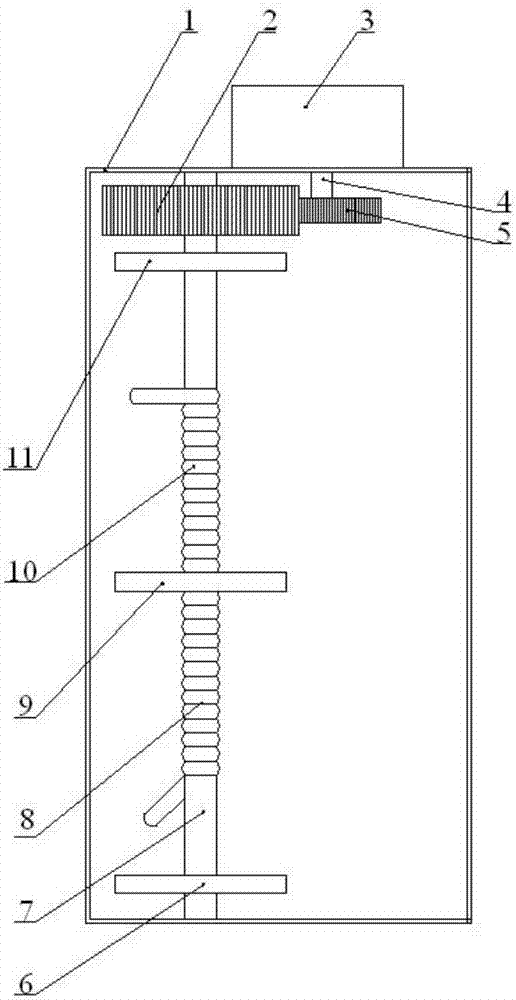
[0018] A two-way drop deceleration device, such as figure 1 As shown, it includes a casing 1, a drive shaft and a rope, and the drive shaft is arranged in the casing. The innovation of the present invention is:

[0019] 1. The drive shaft includes a drive shaft 7 and a driven shaft 4, the drive shaft is eccentrically installed between the upper top surface and the lower bottom surface of the housing, and a drive gear 2 is coaxially installed on the drive shaft, The driven shaft and the driving shaft are installed on the inner side of the upper top surface of the casing in parallel, and a driven gear 5 is coaxially sleeved on the driven shaft. The driven gear is meshed and assembled with the driving gear, so A blocking piece 9 is coaxially sleeved in the ...


PUM


Abstract

The invention relates to a bidirectional landing speed-reduction device. The bidirectional landing speed-reduction device comprises a shell, a drive shaft and ropes. The drive shaft comprises a driving shaft and a driven shaft. A driving gear is coaxially mounted on the driving shaft. The driven shaft is coaxially sleeved with a driven gear. The driven gear and the driving gear are assembled in an engaged mode. A centrifugal speed reducer which is coaxial with the driven shaft is mounted on the outer side of the upper top surface of the shell. The bidirectional landing speed-reduction device is scientific and reasonable in design and simple in structure; the bidirectional landing speed-reduction device is different from a unidirectional landing speed-reduction device in that the two ropes are wound on the drive shaft in a bidirectional mode so that both unidirectional landing and bidirectional landing can be achieved, using cost is reduced, and using efficiency is improved; and the bidirectional landing speed-reduction device is suitable for emergent forced landing of airplanes or emergent escape under high-altitude building fires and dangerous conditions and can also be popularized to other application fields.

Description

technical field [0001] The invention belongs to the field of emergency landing auxiliary equipment, and relates to a landing deceleration device, in particular to a two-way landing deceleration device. Background technique [0002] Emergency landing aids are required for emergency landing of aircraft, fire in high-altitude buildings, and emergency escape from danger. In the prior art, one end of a rope is usually fixed, and the other end is tied to the landing personnel or objects. However, during the high-altitude landing, due to the Due to the effect of its own weight, with the increase of displacement, the descending speed continues to increase, resulting in faster and faster descending speed. There is a certain danger, and there is a greater safety hazard for the safety of people and items. Therefore, it is necessary to pass certain measures. The deceleration means or deceleration device realizes the deceleration of the landing. Through the retrieval of the prior art, no...

Claims


Application Information

Patent Timeline
Patent Type & Authority Applications(China)
IPC IPC(8): A62B1/06
CPCA62B1/06
Inventor 刘睿达
Owner 刘睿达
Why Eureka
Try Eureka