Device and method for separating suspended micro-oil-fume particles on range hood

A technology for particle separation and tiny particles, applied in separation methods, dispersed particle separation, combined devices, etc., can solve problems such as electrostatic and mechanical methods that cannot be caught

Inactive Publication Date: 2017-09-19
HANGZHOU ROBAM APPLIANCES CO LTD
View PDF5 Cites 0 Cited by
  • Summary
  • Abstract
  • Description
  • Claims
  • Application Information

AI Technical Summary

Problems solved by technology

However, no matter which method is used, the large oil fume particles are filtered, and the smaller oil fume particles cannot be caught by electrostatic and mechanical methods.

Method used


Image

  • Device and method for separating suspended micro-oil-fume particles on range hood
  • Device and method for separating suspended micro-oil-fume particles on range hood
  • Device and method for separating suspended micro-oil-fume particles on range hood

Examples


Embodiment 1

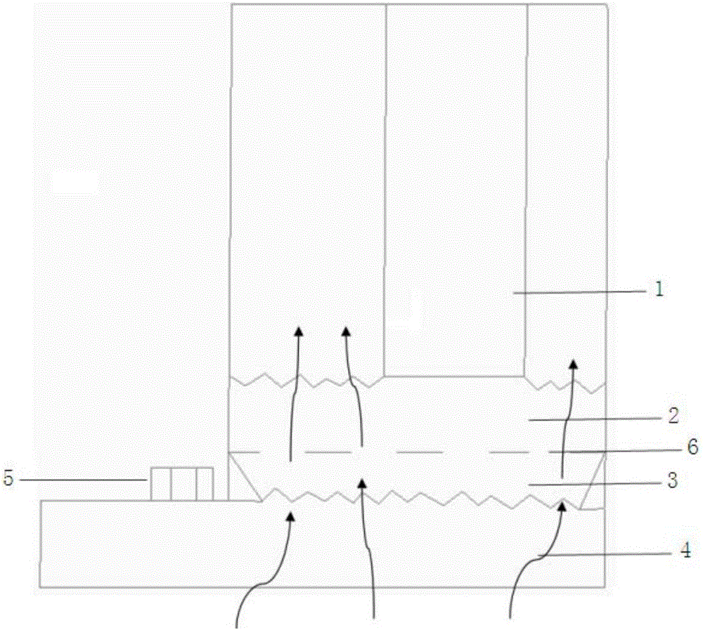
[0030] Embodiment one: as attached figure 1 As shown, the suspended micro fume particle separation device on the range hood includes a range hood body 1 and a range hood collecting device 4. The range hood collecting device 4 is located below the range hood body 1 and further includes Oil fume velocity slowing condenser 3, rectification net 6, oil fume water molecule collision mixing condenser 2 and cold water particle generator 5 located on range hood body 1, said oil fume velocity slowing condenser 3, rectification net 6, oil fume water The molecular collision mixing condenser 2 is located above the oil fume collecting device 4 , and the cold water micro particles generated by the cold water micro particle generator 5 are sprayed in the oil fume velocity slowing condenser 3 and / or the oil fume water molecule collision mixing condenser 2 .

Embodiment 2

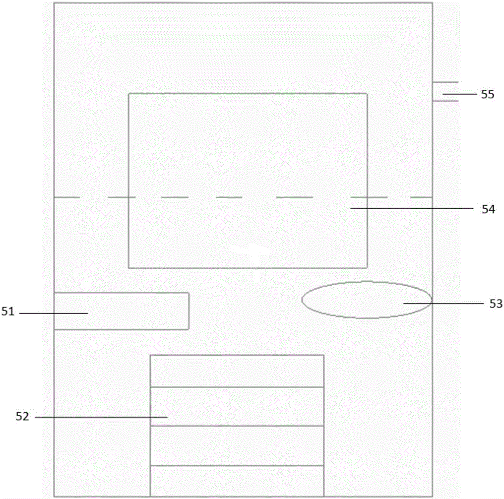
[0031] Embodiment 2: In the foregoing embodiment, as attached Figure 4 As shown, the oil fume water molecule collision mixing condenser 2 is provided with a channel communicating with the cold water particle generator 5, and the side wall of the oil fume water molecule collision mixing condenser 2 is provided with a plurality of The water molecule collision mixing condenser 2 is a water mist spray nozzle for spraying water mist inside; specifically: a left water mist spray nozzle 22 and a right water mist spray nozzle 21 can be respectively provided on both sides; In the device 2, the atomized water mist is sprayed on the area through a reasonable arrangement of water mist nozzles to form a certain concentration. Atomized water molecules collide and mix thoroughly.

Embodiment 3

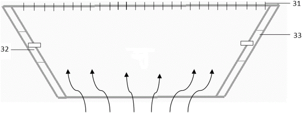
[0032] Embodiment three: In the above embodiment, as attached figure 2 As shown, the oil fume flow velocity slowing condenser 3 is an inverted trapezoidal structure, and the cross-sectional area of ​​the oil smoke flow velocity slowing condenser 3 gradually increases according to the flow direction of the flue gas. According to the Venturi effect, the oil fume flow rate through the oil fume flow rate slowing condenser 3 can be effectively slowed down, reaching a speed that can effectively condense water molecules and oil smoke, and the cold water tiny particles sprayed in the oil smoke flow rate slowing condenser 3 are in and tiny During the condensation process of soot particles, the temperature of tiny soot particles can be cooled.


PUM


Abstract

The invention relates to a device and a method for separating suspended micro-oil-fume particles on a range hood. The device comprises a range hood body, an oil fume collection device, an oil fume flow velocity deceleration condenser, a rectification screen, an oil fume water molecule collision mixing condenser and a cold water micro-particle generator, the oil fume collection device is positioned below the range hood body, the oil fume flow velocity deceleration condenser, the rectification screen and the oil fume water molecule collision mixing condenser are sequentially fixed on the range hood body, the cold water micro-particle generator is positioned on the range hood body, the oil fume flow velocity deceleration condenser, the rectification screen and the oil fume water molecule collision mixing condenser are positioned on the oil fume collection device, and cold water micro-particles generated by the cold water micro-particle generator are sprayed into the oil fume flow velocity deceleration condenser and / or the oil fume water molecule collision mixing condenser. According to the device, condensation growth of micro-oil-fume particles is achieved, and the micro-oil-fume particles are easily filtered out by a traditional filtering device.

Description

technical field [0001] The invention belongs to the technical field of range hoods, and in particular relates to a separation device and method for suspended micro fume particles on a range hood. Background technique [0002] At present, the country pays more attention to environmental protection. There are many kinds of grease separation methods in the field of household range hoods. The main mechanical filter method used in household range hoods, and the main method of industrial use are electrostatic and other methods. However, no matter which method is used, the large fume particles are filtered, and the smaller fume particles cannot be captured by electrostatic and mechanical methods. Contents of the invention [0003] The purpose of the present invention is to overcome the deficiencies in the prior art, and provide a device and method for separating tiny oil fume particles suspended on a range hood. The method can easily be filtered out by traditional filter devices ...

Claims


Application Information

Patent Timeline
Patent Type & Authority Applications(China)
IPC IPC(8): B01D50/00F24C15/20
CPCF24C15/2035F24C15/2057B01D50/60
Inventor 任富佳南江
Owner HANGZHOU ROBAM APPLIANCES CO LTD
Why Eureka
Try Eureka