Groove machining method

A processing method and technology to be processed, applied in the field of groove processing, can solve the problems of built-up edge, long overhang length of groove insert, and difficulty in discharging iron chips, so as to improve processing quality and efficiency, enhance processing stability, The effect of reducing production costs

Active Publication Date: 2017-09-19
GUIZHOU LIYANG INT MFG
View PDF5 Cites 9 Cited by
  • Summary
  • Abstract
  • Description
  • Claims
  • Application Information

AI Technical Summary

Problems solved by technology

[0002] In the machining industry, grooves are a common feature on parts. For example, on the parts of a certain type of aero-engine, grooves are designed on the workpiece. The depth of the groove is 20 mm and the width is about 115 mm. In the prior art, Generally, groove inserts are used to cut grooves, and the processing process has the following defects: because the grooves are deep and wide, the width of the grooves is about 5 times the depth of the grooves. On the other hand, since the iron filings are not discharged in time during the cutting process and remain in the groove, when the iron filings accumulate in the groove, any damage generated during the cutting process will be caused. If the light cannot be discharged in time, it is easy to cause chip jamming and built-up edge, which will cause chipping of the groove cutter and affect the surface processing quality of the workpiece, especially the surface roughness of the workpiece cannot meet the design requirements. In addition, during processing During the process, the cutting parameters of the groove blade are low, and the processing efficiency of the groove is very low. Due to the long overhang length and poor rigidity of the groove blade, the blade vibration phenomenon is easy to occur, which affects the service life of the groove blade and affects the machining efficiency.

Method used


Image

  • Groove machining method
  • Groove machining method

Examples


Embodiment Construction

[0033] The technical scheme of the present invention will be further described below in conjunction with the accompanying drawings, but the required protection scope is not limited to the description;

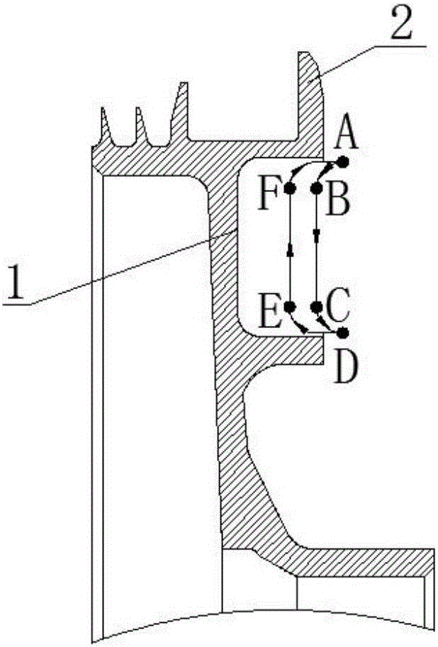
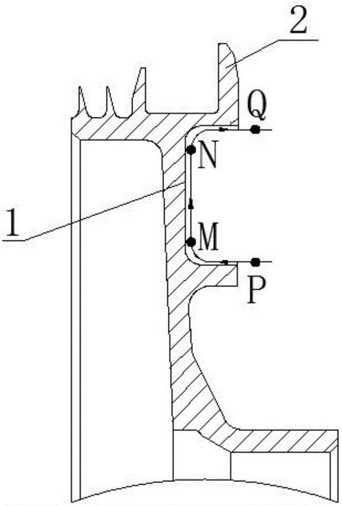
[0034] The invention provides a method for processing grooves, such as figure 1 , figure 2 shown, including the following steps:

[0035] Step 1: prepare the blank; using the technical scheme provided by the present invention, the blank can be a cylinder or a cuboid. When a cylinder is used, the groove processing can be completed on a CNC lathe. When the blank is a cuboid, it can be The groove machining is done on the machining center.

[0036] Step 2: Draw the edge line of the area to be processed on the blank in step 1; using the technical solution provided by the present invention, the line of the area to be processed has at least a pair of opposite edge lines to improve the processing accuracy of the subsequent processing procedure, and the required processing The forme...


PUM

PropertyMeasurementUnit
thicknessaaaaaaaaaa
widthaaaaaaaaaa

Abstract

The invention relates to a groove machining method. The groove machining method comprises the steps that firstly drawing side boundaries of a to-be-machined area on a blank; using a hard alloy square head groove blade to conduct rough machining on the blank to enable the hard alloy square head groove blade to move back and forth between two opposite side boundaries of the to-be-machined area; using a hard alloy round head groove blade to conduct finish machining on the blank to enable the hard alloy round head groove blade to move along the machined profile and machine the remaining allowance. By utilizing the technical scheme, different blades are used in the rough machining and finish machining stages, the blade swings back and forth in the to-be-machined area in rough machining, a combination of a straight line machining route and a curve machining route is utilized, the feed speed of the straight line machining route is high, the feed speed of the curve machining route is low, blade machining rigidity is improved, phenomena such as clip clamping and tool tipping are avoided, machining stability is enhanced, vibration of the blades in the cutting process is reduced, machining quality and efficiency are improved, and production cost is reduced.

Description

technical field [0001] The invention relates to the field of mechanical processing, in particular to a method for processing grooves. Background technique [0002] In the machining industry, grooves are a common feature on parts. For example, on the parts of a certain type of aero-engine, grooves are designed on the workpiece. The depth of the groove is 20 mm and the width is about 115 mm. In the prior art, Generally, groove inserts are used to cut grooves, and the processing process has the following defects: because the grooves are deep and wide, the width of the grooves is about 5 times the depth of the grooves. On the other hand, since the iron filings are not discharged in time during the cutting process and remain in the groove, when the iron filings accumulate in the groove, any damage generated during the cutting process will be caused. If the light cannot be discharged in time, it is easy to cause chip jamming and built-up edge, which will cause chipping of the gro...

Claims


Application Information

Patent Timeline
Patent Type & Authority Applications(China)
IPC IPC(8): B23P15/00
CPCB23P15/00
Inventor 王俊伟王涛吴德宁郭文光杨韬沈欢
Owner GUIZHOU LIYANG INT MFG
Why Eureka
Try Eureka