
Automatic assembly machine for nesting screw lamp holder on lamp body

A screw lamp holder and assembly machine technology, which is applied in the direction of lighting devices, semiconductor devices of light-emitting elements, light sources, etc., can solve problems such as difficult to realize automation, difficult to pass through holes, and uncertain positions, so as to achieve the effect of automation

Pending Publication Date: 2017-09-19
迈杰特科技(厦门)有限公司
View PDF7 Cites 4 Cited by
  • Summary
  • Abstract
  • Description
  • Claims
  • Application Information

AI Technical Summary

Problems solved by technology

[0004] When assembling the screw LED light bulb, the screw lamp cap needs to be placed on the lamp body, and the wires on the lamp body used to connect with the live wire need to pass through the through hole on the top of the screw lamp cap. It is often skewed and the position is very uncertain, so it is difficult to pass through the through hole accurately. Therefore, in actual production, the installation of the screw lamp cap is mostly a semi-automatic production method that manually sets the screw cap, and it is difficult to achieve true automation.

Method used


Image

  • Automatic assembly machine for nesting screw lamp holder on lamp body
  • Automatic assembly machine for nesting screw lamp holder on lamp body
  • Automatic assembly machine for nesting screw lamp holder on lamp body

Examples


Embodiment Construction

[0058] In order to further explain the technical solution of the present invention, the present invention will be described in detail below through specific examples.

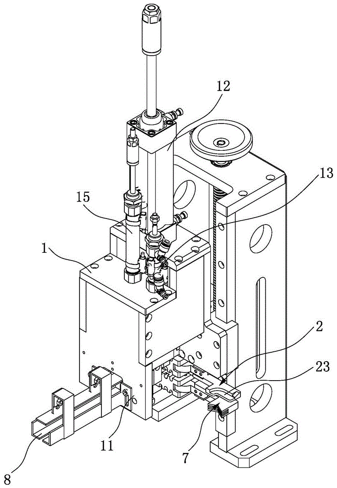
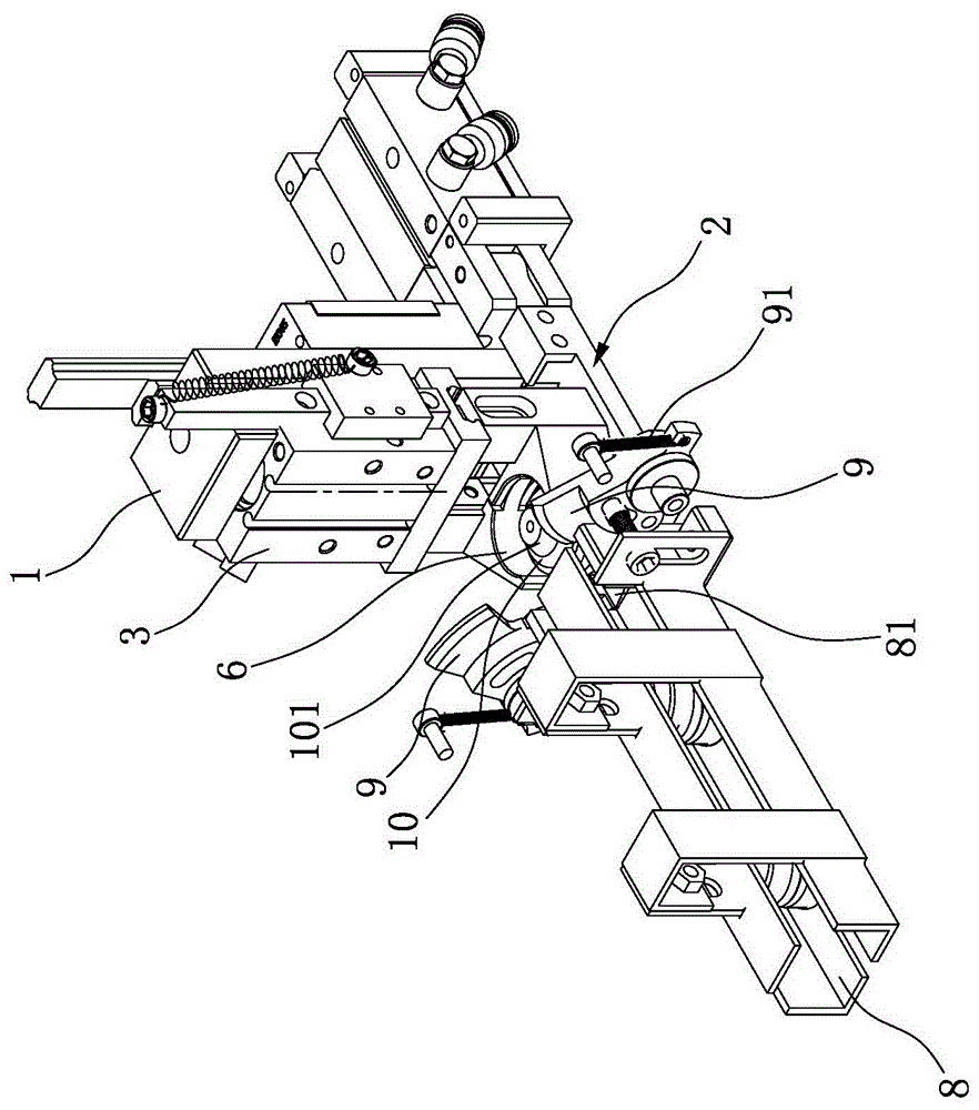
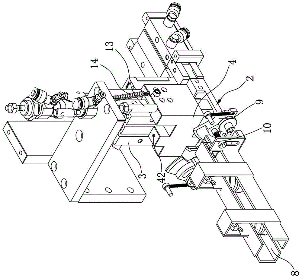
[0059] combine figure 1 , Figure 4 and Figure 8 As shown, the present invention discloses an automatic assembly machine for placing the screw cap on the lamp body, mainly including a frame 1, a pneumatic receiving claw 2, a socket 3, a positioning seat 4, a needle tube 5, and a pneumatic screw Holding claw 6, pneumatic wire holding claw 7 and controller.

[0060] The pneumatic receiving claw 2 is installed on the frame 1, such as Figure 4As shown, it consists of a left receiving claw 21 and a right receiving claw 22 that can be opened and closed. When the pneumatic receiving claw 2 is closed, its upper surface is used to receive and place the screw lamp cap 10 . As an optimization, the upper surfaces of the left receiving claw 21 and the right receiving claw 22 jointly form a receiving groove 23, and the...


PUM


Abstract

The invention discloses an automatic assembly machine for nesting a screw lamp holder on a lamp body. The automatic assembly machine mainly comprises a rack, pneumatic receiving claws, a nesting base, a positioning base, a needle pipe, pneumatic screw holding claws, pneumatic electric wire holding claws and a controller. When the automatic assembly machine works, the pneumatic receiving claws close, the screw lamp holder is put on the upper surfaces of the pneumatic receiving claws, and then the positioning base moves downwards so as to position the screw lamp holder; afterwards, the pneumatic screw holding claws tightly hold the screw lamp holder, then the pneumatic receiving claws open, and the pneumatic electric wire holding claws tightly hold electric wires extending out from the lamp body so as to position the electric wires; afterwards, the needle pipe moves downwards to pass through a through hole of the head of the screw lamp holder and continuously moves downwards till the electric wires are inserted into the interior of the needle pipe, the electric wires are positioned by the needle pipe at the moment, then the pneumatic electric wire holding claws open, the whole nesting base moves downwards, and finally the whole screw lamp holder is nested on the lamp body. The automatic assembly machine has the beneficial effects that the electric wires can accurately pass through the screw lamp holder in the process of nesting the screw lamp holder on the lamp body, and the automation of screw lamp holder installation is realized.

Description

technical field [0001] The invention relates to the technical field of LED light bulb production, in particular to an automatic assembly machine for placing a screw cap cap on a lamp body. Background technique [0002] Traditional incandescent lamps (tungsten filament lamps) have high energy consumption and short lifespan. Under the environment of global resource shortage, their production has been gradually banned by governments of various countries. The replacement products are electronic energy-saving lamps. Although electronic energy-saving lamps have improved energy-saving effects, However, due to the use of many heavy metal elements that pollute the environment, it is contrary to the general trend of environmental protection. With the rapid development of LED technology, LED lighting has gradually become the best choice for new green lighting. LED is far superior to traditional lighting products in terms of luminous principle, energy saving and environmental protectio...

Claims


Application Information

Patent Timeline
IPC IPC(8): B23P19/04F21K9/90
CPCF21K9/90B23P19/04F21Y2115/10
Inventor 张冲文
Owner 迈杰特科技(厦门)有限公司
Learn More