Method for recording subsurface structure and directly imaging by utilizing micro-earthquake

A technology of underground structure and recording pair, applied in seismology, geophysical measurement, seismic signal processing, etc., can solve the problem of poor deep imaging effect, and achieve the effect of improving imaging effect, accurate incident field, and saving computing time.

Inactive Publication Date: 2017-09-19
JILIN UNIV
View PDF6 Cites 7 Cited by
  • Summary
  • Abstract
  • Description
  • Claims
  • Application Information

AI Technical Summary

Problems solved by technology

This method does not need to separate individual microseismic events, but the effective information it uses is actually free surface multiple waves, so the deep imaging effect is not very good

Method used


Image

  • Method for recording subsurface structure and directly imaging by utilizing micro-earthquake
  • Method for recording subsurface structure and directly imaging by utilizing micro-earthquake
  • Method for recording subsurface structure and directly imaging by utilizing micro-earthquake

Examples


Embodiment 1

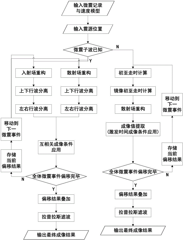
[0093] A. Input microseismic records and underground velocity models;

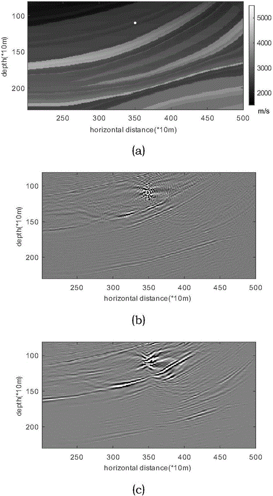
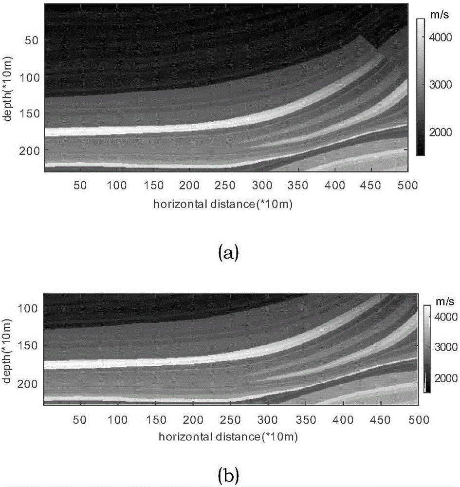
[0094] The method is verified by numerical experiments. Various parameters such as the model and observation system used are as follows: forward velocity model and migration velocity model such as image 3 As shown in (a), it is a relatively gentle part of the interface in the Marmousi model; the model size is 230*500, the grid spacing is 10m, 250 receiver points are evenly distributed on the surface at a spacing of 20m, and the time sampling interval is 1ms. The wavelets of the events all adopt the 30Hz Reck wavelet. Set the microseismic position, excitation time and wavelet as known quantities, that is, this example tests the cross-correlation imaging condition;

[0095] B. Input the source location;

[0096] Since this method only regards the imaging results below the seismic source as valid information, the seismic source location of the example is set in the shallow part of the ground, specifically...

Embodiment 2

[0109] a. Input microseismic records and underground velocity models;

[0110] The method is verified by numerical experiments. Various parameters such as the model and observation system used are as follows: forward velocity model and migration velocity model such as image 3 As shown in (a), it is a relatively gentle part of the interface in the Marmousi model; the model size is 230*500, the grid spacing is 10m, 250 receiver points are evenly distributed on the surface at a distance of 20m, and the time sampling interval is 1ms. The wavelets of the events all adopt the 30Hz Reck wavelet. The position and excitation time of microseisms are set as known quantities, while the wavelet is an unknown quantity, that is, the imaging conditions of excitation time are tested in this example;

[0111] b. Input the source location;

[0112] Since this method only regards the imaging results below the seismic source as valid information, the seismic source location of the example is s...


PUM


Abstract

The invention relates to a method for recording subsurface structure and directly imaging by utilizing micro-earthquake, micro-earthquake position and a wavelet are assumed to be known, reverse time migration is directly used, cross-correlation imaging conditions are adopted, a micro-earthquake event is served as a boundary condition for incident field reconstruction, a timeline-inversed micro-earthquake record is served as a boundary condition for scattered field reconstruction, and imaging is performed on a subsurface structure. According to the invention, the micro-earthquake event is served as the boundary condition for incident field reconstruction, the incident field precision of deep medium is effectively improved, and the deep medium imaging effect from the direct imaging method is effectively improved. Scattered micro-earthquake event can image without requirements of properties such as amount, density, distribution and the like of micro-earthquake; the micro-earthquake event is adopted to reconstruct the incident field, so that the incident field below a seismic source is more precise; a method for up and down wave separation and left and right wave separation is used for depressing high-frequency and low-frequency noises, solving wavelet shape is avoided, and plenty of calculation time is saved.

Description

Technical field: [0001] The invention relates to an imaging problem of deep underground structures of geological bodies, in particular to a method for directly imaging underground structures by using microseismic records. Background technique: [0002] Imaging subsurface structures using passive source records is one of the important research points in the field of passive sources. Whether it is a microseismic event or environmental noise, the current conventional method for imaging structures is to first reconstruct active source records, and then use the reconstructed records for imaging. The use of passive source records to reconstruct active source records originated from the "acoustic daylight imaging" proposed by Claerbout (1985. Imaging the earth's interior. Geophysical Journal of the Royal Astronomical Society 86(1). 217-217). This method proves that: The transmitted wave records from the subsurface to the surface are autocorrelated, and the results are equivalent t...

Claims


Application Information

Patent Timeline
Patent Type & Authority Applications(China)
IPC IPC(8): G01V1/34
CPCG01V1/345G01V2210/74
Inventor 葛奇鑫韩立国
Owner JILIN UNIV
Why Eureka
Try Eureka