
Method for realizing rapid load pulling based on power grid topology structure

A grid topology and fast technology, applied in electrical components, circuit devices, emergency protection circuit devices, etc., can solve problems such as inability to effectively solve the problem of identification, failure to achieve fast load loading, complex algorithm logic, etc., to avoid grid collapse. The effect of events, avoiding long load shedding time, and simple algorithm logic

Active Publication Date: 2017-09-19
QUANZHOU POWER SUPPLY COMPANY OF STATE GRID FUJIAN ELECTRIC POWER +1
View PDF3 Cites 5 Cited by
  • Summary
  • Abstract
  • Description
  • Claims
  • Application Information

AI Technical Summary

Problems solved by technology

Even so, at the implementation level, since load loading is generally performed on the power supply side of the 220 kV substation, under the condition that the configuration of automatic safety devices in the power grid is increasingly perfect, the implementation of load loading will often cause the action of the standby automatic switching device, which often requires two Only one round of multi-switch operations can perform the loading operation, which will take a long time and may cause overload of other normal operating equipment, which will not meet the requirements of fast loading and increase the risk of expanding the scope of accidents; The idea of ​​pulling and stopping the load on the power supply side is still continued, and the focus is on the screening of the action switch of the safety automatic device and the secondary pull. Screening problems, design ideas have certain flaws

Method used


Image

  • Method for realizing rapid load pulling based on power grid topology structure
  • Method for realizing rapid load pulling based on power grid topology structure
  • Method for realizing rapid load pulling based on power grid topology structure

Examples


Embodiment Construction

[0028] The present invention will be further described below through specific embodiments.

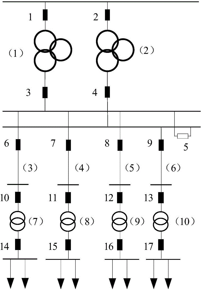
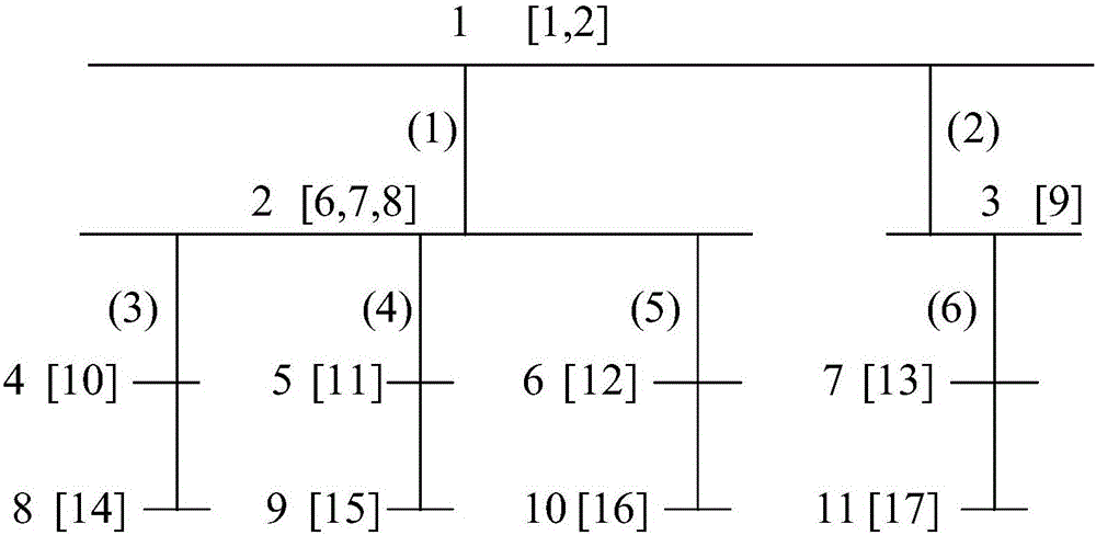
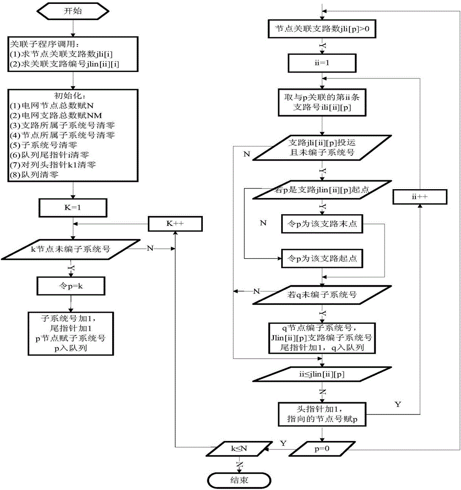
[0029] refer to Figure 1 to Figure 4 , a kind of method of the present invention is based on power grid topological structure and realizes fast pulling load, comprises the following steps:

[0030] ①Based on the SCADA module of the integrated technical support system for power grid regulation, data acquisition, drawing modeling, platform management, real-time data maintenance and remote control channels fully utilize the existing functions of the SCADA module and expand the functions to make full use of various telemetry of the entire network , Remote signaling information, combined with various accidents, super power supply capacity limit management regulations and grid structure, embedded grid topology analysis rules and parallel control technology algorithms.

[0031] The parallel control technology provides visualization and interactive operation of the control process, including...


PUM


Abstract

Provided is a method for realizing rapid load pulling based on a power grid topology structure. Based on a power grid control integrated technology support system, embedded power grid topology analysis rules, and the parallel control technology, the end load switch can be rapidly positioned through power grid topology analysis and the one-button batch load pulling is realized by means of the parallel remote control technology. By changing the common thought about conventional power grid load pulling, the load pulling operation is executed on the power grid end load side switch, and the rapid load pulling can be realized when the power grid has big accidents, the method provided is not influenced by the power grid operation mode and the equipment state, is high in reliability, can make valuable golden time for serious power grid accidents, and effectively prevent power grid breakdown events. In the case of an accident, the accident handling time and the power failure range can be maximally reduced, and the user's bad feelings can be reduced. Moreover, the artificial workload can be effectively reduced, the work efficiency and work quality of accident emergent load pulling management can be improved, and good economic and social benefits can be guaranteed.

Description

technical field [0001] The invention relates to a power grid fault processing method, in particular to a method for realizing rapid loading based on the power grid topology. Background technique [0002] With the operation of nuclear power projects and UHV projects, the external environment and factors of power grid operation have become increasingly complex, and the requirements for safe and stable operation have been greatly increased; The reasons for power outages are complex and diverse. However, after a major accident occurs in the power grid, quickly pulling down the load is often the most direct and effective measure to ensure the stability of the power grid. The purpose of a series of emergency measures is to construct the last line of defense to ensure the safety of the power grid and prevent large-scale power outages caused by voltage and frequency collapse. Even so, at the implementation level, since load loading is generally performed on the power supply side of...

Claims


Application Information

Patent Timeline
Patent Type & Authority Applications(China)
IPC IPC(8): H02J13/00H02H7/26
CPCH02J13/0017H02H7/26H02J13/00001Y02E60/00Y04S10/20
Inventor 陈厚荣兰翠芸陈梅珍刘丽莎潘玮明李毅鹏许鹏
Owner QUANZHOU POWER SUPPLY COMPANY OF STATE GRID FUJIAN ELECTRIC POWER
Learn More