
Rotor alternate-angle stator magnetic isolation type axial permanent magnet auxiliary double-salient-pole motor

A double salient motor, angular stator technology, applied to synchronous motors with stationary armatures and rotating magnets, magnetic circuit shape/pattern/structure, magnetic circuit, etc., can solve the torque ripple of ordinary salient reluctance motors Large, magnetic flux loss wastes energy and other problems, to achieve good magnetic permeability, reduce copper loss, reduce the effect of reducing the moment of inertia

Pending Publication Date: 2017-09-19
SHENYANG POLYTECHNIC UNIV
View PDF12 Cites 8 Cited by
  • Summary
  • Abstract
  • Description
  • Claims
  • Application Information

AI Technical Summary

Problems solved by technology

[0002] As the most commonly used doubly salient motor, switched reluctance motor is developing rapidly. The driving circuit of switched reluctance motor is simple, and it can maintain high-efficiency operation in a wide speed range. However, the torque ripple of ordinary salient reluctance motor Larger, the yoke flux loss between adjacent stator teeth is large and wastes energy

Method used


Image

  • Rotor alternate-angle stator magnetic isolation type axial permanent magnet auxiliary double-salient-pole motor
  • Rotor alternate-angle stator magnetic isolation type axial permanent magnet auxiliary double-salient-pole motor
  • Rotor alternate-angle stator magnetic isolation type axial permanent magnet auxiliary double-salient-pole motor

Examples


Embodiment Construction

[0031] An embodiment of the present invention will be described in detail below with reference to the accompanying drawings.

[0032] like Figure 1-9 As shown, a rotor staggered stator magnetic isolation axial permanent magnet assisted doubly salient motor, comprising:

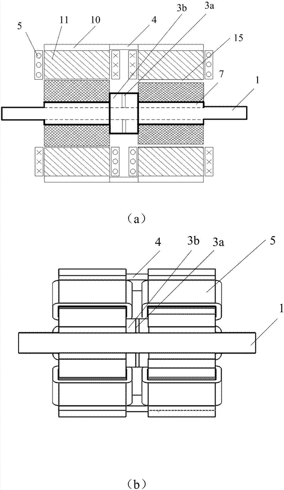
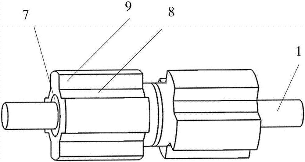
[0033] Two sets of magnetic isolation stators, two sets of circumferentially staggered rotors, a rotating shaft 1, a casing 2, an axial ring-sleeved composite permanent magnet 3, a magnetic strip 4, an excitation winding 5 and an end cover 6.

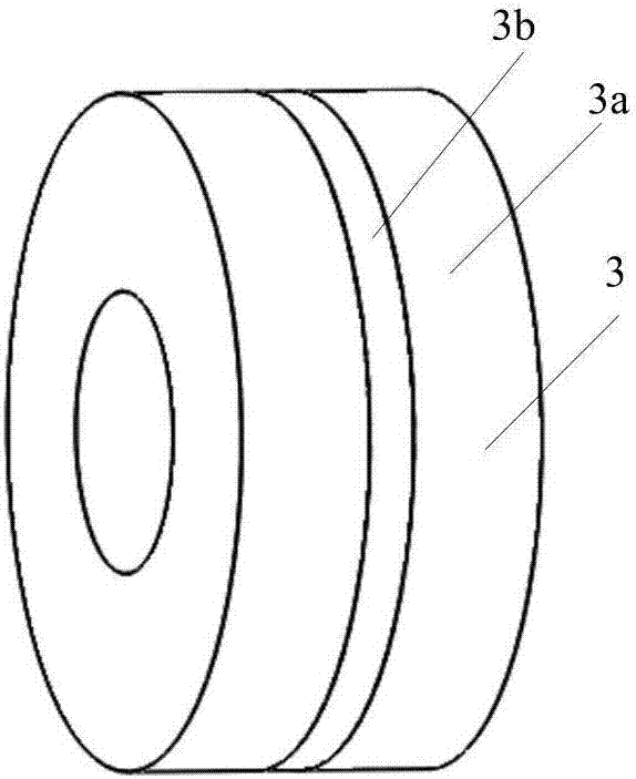
[0034] like figure 2 As shown, the axial ring-sleeve type composite permanent magnet 3 includes a permanent magnet 3b and a magnetic conductor 3a bonded at both ends thereof, and the axial ring-sleeve type composite permanent magnet 3 is ring-sleeved at the central position of the rotating shaft, and there is a space between it and the rotating shaft. A certain gap; the magnetic conductive material 3a is made of magnetic conductive material.

[0035] The rotating s...


PUM


Abstract

The invention provides a rotor alternate-angle stator magnetic isolation type axial permanent magnet auxiliary double-salient-pole motor and belongs to the field of double-salient-pole reluctance motors. The double-salient-pole motor comprises two groups of magnetic isolation type stators, two groups of circumferentially alternate-angle rotors, a rotating shaft, a casing, an axial ring sleeve type composite permanent magnet, a magnetic conduction strip and exciting windings. The axial ring sleeve type composite permanent magnet is annularly sleeved at the center of the rotating shaft. The two groups of circumferentially alternate-angle rotors are fixed on the rotating shaft on both sides of the axial ring sleeve type composite permanent magnet. Each magnetic isolation type stator comprises a partitioned stator yoke and a salient pole and each salient pole is wound with one exciting winding. The magnetic isolation type stators and the circumferentially alternate-angle rotors are correspondingly arranged and an air gap is arranged. The casing and the rotating shaft are coaxial. The inner wall of the casing is provided with six magnetic isolation strips. The magnetic isolation type stators are fixed in the magnetic isolation grooves of the casing. The magnetic conduction strip is used for connecting stators on the two sides to be served as a magnetic bridge. According to the invention, the output torque is effectively improved and the armature current is reduced in certain conditions. The torque ripple of the motor is improved and the loss of the yoke part of each stator is lowered. Therefore, the operating efficiency of the motor is improved and the performance indexes of the motor are better.

Description

technical field [0001] The invention belongs to the field of doubly salient reluctance motors, in particular to a rotor staggered stator magnetic isolation axial permanent magnet auxiliary doubly salient motor. Background technique [0002] As the most commonly used double salient motor, the switched reluctance motor is developing rapidly. The switched reluctance motor has a simple drive circuit and can maintain efficient operation in a wide speed range. However, the torque ripple of the ordinary salient stage reluctance motor Larger, the magnetic flux loss of the adjacent stator inter-tooth yoke is large and wastes energy. SUMMARY OF THE INVENTION [0003] In view of the above-mentioned deficiencies in the prior art, the present invention provides a rotor staggered stator magnetic isolation axial permanent magnet assisted doubly salient motor, which can effectively increase the output torque and reduce the armature current under certain conditions. , improve the torque r...

Claims


Application Information

Patent Timeline
Patent Type & Authority Applications(China)
IPC IPC(8): H02K16/00H02K21/24H02K1/14H02K1/24
CPCH02K1/145H02K1/24H02K16/00H02K21/24Y02T10/64
Inventor 刘爱民李家尧娄家川孙鹏高智超韦有帅任达李博
Owner SHENYANG POLYTECHNIC UNIV
Learn More