Grain unloading device of harvester

A grain unloading device and harvester technology, applied in harvesters, cutters, agricultural machinery and implements, etc., can solve the problems of grain pollution, oil leakage of hydraulic cylinders, etc., and achieve the effect of avoiding pollution

Pending Publication Date: 2017-09-22
ZOOMLION HEAVY MASCH CO LTD
View PDF8 Cites 0 Cited by
  • Summary
  • Abstract
  • Description
  • Claims
  • Application Information

AI Technical Summary

Problems solved by technology

[0002] The closest existing technology to the present invention is the patent (Patent No.: 201220470297.4) entitled "Grain Combine Harvester Unloading Auger", the grain tank is fixed to the frame platform, the grain unloading cylinder is located above the grain tank, The end is fixedly connected with the swivel elbow, and the hydraulic cylinder used to drive the swivel elbow is located in the grain tank. The disadvantage of this patent is that the hydraulic cylinder is located in the grain tank. Since the hydraulic cylinder has the hidden danger of oil leakage, the There is a risk of contamination of the grain in the grain bin

Method used


Image

  • Grain unloading device of harvester

Examples


Embodiment 1

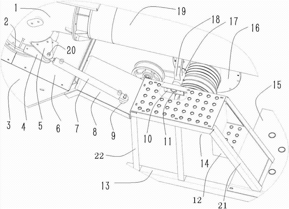
[0021] like figure 1 As shown, the grain tank 3 is fixed to the frame platform 15, the grain unloading cylinder 19 is located above the grain tank 3, the end of the grain unloading cylinder 19 is fixedly connected to the rotary elbow 1 by bolts, and the position of the entrance of the rotary elbow 1 and the outlet of the grain tank 3 Correspondingly, this is the prior art. Hydraulic cylinder 7 (comprising supporting hydraulic element, hydraulic pipeline) is positioned at the outside of grain tank 3, and the cylinder rod end of hydraulic cylinder 7 is hinged with swivel elbow 1, and the cylinder end of hydraulic cylinder 7 is hinged with holder 8. During specific implementation, the lower part of the swivel elbow 1 is provided with a boss, the boss is provided with a mounting hole, the upper connecting plate 5 and the lower connecting plate 4 are provided with a mounting circular hole, and the upper connecting plate 5 and the lower connecting plate 4 pass through the bolts. Co...

Embodiment 2

[0025] like figure 1 As shown, the drive unit of the grain unloading cylinder includes a motor, a clutch support shaft 17, a clutch arm 18, and the motor output end 16 is fixedly connected to the motor. Engine output end 16 is provided with clutch supporting shaft 17, and clutch rotating arm 18 is installed on the clutch supporting shaft 17, and the parts installed on clutch rotating arm 18 and its top can rotate with clutch supporting shaft 17. The clutch arm 18 is connected with the clutch control device, and the driver can operate the control device in the cab so as to realize the rotation of the clutch arm 18 and the opening and closing of the clutch, which is prior art.

[0026] In the second embodiment, the maintenance ladder 14 is located on the left side of the engine, and the top pedal of the maintenance ladder is provided with a support seat, which is used to support the clutch support shaft 17 of the grain unloading cylinder drive unit. The support seat is composed...

Embodiment 3

[0028] The difference between the third embodiment and the second embodiment is that the two ends of the fixing base 8 are provided with waist holes for adjusting the installation position. The seat plate 10 is provided with a horizontal waist hole for adjusting the installation position, and the maintenance ladder top surface pedal is correspondingly provided with a vertical waist hole for adjusting the installation position.


PUM


Abstract

The invention relates to a grain unloading device of a harvester. The grain unloading device comprises a grain box and a grain unloading cylinder, the grain box is fixed to a machine frame platform, the grain unloading cylinder is located above the grain box, and the end of the grain unloading cylinder is fixedly connected with a rotating bend; an inlet of the rotating bend corresponds to the position of an outlet of the grain box, and a hydraulic oil cylinder is located outside the grain box; the end of a cylinder rod of the hydraulic oil cylinder is hinged to the rotating bend; the end of a cylinder body of the hydraulic oil cylinder is hinged to a fixing base. The hydraulic oil cylinder is arranged outside the grain box, so that the problem that grains in the grain box are contaminated due to oil leakage of the hydraulic oil cylinder is fundamentally solved.

Description

technical field [0001] The invention relates to a harvester grain unloading device. Background technique [0002] The closest existing technology to the present invention is the patent (Patent No.: 201220470297.4) entitled "Grain Combine Harvester Unloading Auger", the grain tank is fixed to the frame platform, the grain unloading cylinder is located above the grain tank, The end is fixedly connected with the swivel elbow, and the hydraulic cylinder used to drive the swivel elbow is located in the grain tank. The disadvantage of this patent is that the hydraulic cylinder is located in the grain tank. Since the hydraulic cylinder has the hidden danger of oil leakage, the There is a risk of contamination of the grain in the grain bin. Contents of the invention [0003] The object of the present invention is to provide a grain unloading device for a harvester, which can effectively prevent the grain in the grain tank from being polluted by the oil leakage of the hydraulic cy...

Claims


Application Information

Patent Timeline
IPC IPC(8): A01D41/12
CPCA01D41/1217
Inventor 丁正耀唐艳荣张季张礼徐于士兵李树波丁丽潘晶祁晶胡冰
Owner ZOOMLION HEAVY MASCH CO LTD
Why Eureka
Try Eureka