Fixation device beneficial to fixation and healing of patella fracture

A fixation device and a technology for patellar fractures, applied in the direction of fixators, internal fixators, and internal bone synthesis, can solve problems such as destroying local blood supply, delaying fracture healing, and affecting fracture healing, achieving blood supply protection, small trauma, and Favorable effect on fracture healing

Pending Publication Date: 2017-09-22
陈卫
View PDF9 Cites 0 Cited by
  • Summary
  • Abstract
  • Description
  • Claims
  • Application Information

AI Technical Summary

Problems solved by technology

However, it was found during the operation that when the patella needle was used for fixation, the steel wire on the other side of the needle door was locked tightly by the needle door after the steel wire passed through the needle door. Needle-tightened wire, prone to wire breakage, needs to be re-fixed, and hard to twist, loosening the tension band
At the same time, for elderly patients, patients with multiple fractures, and patients with poor general conditions, it is necessary to use an electric knife or a round knife to cut and separate the fascia and ligament tissue on the surface of the patella to accommodate the steel wire before winding the steel wire along the steel wire. Local blood supply affects fracture healing, and some patients experience delayed fracture union or even nonunion

Method used


Image

  • Fixation device beneficial to fixation and healing of patella fracture
  • Fixation device beneficial to fixation and healing of patella fracture
  • Fixation device beneficial to fixation and healing of patella fracture

Examples


Embodiment Construction

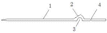
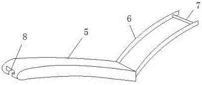
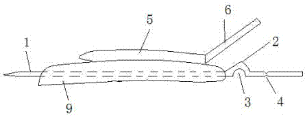
[0017] The present invention comprises fixed needle 1, wire feeding plate 5, push rod 6, handle 7.

[0018] figure 1 , 3 It shows that the needle body of the fixation pin 1 is a Kirschner wire, and the rear part of the needle body of the fixation pin 1 has a limit protrusion 2, the limit protrusion 2 is conical, and the conical small diameter end of the limit protrusion is opposite to the patella . The position of the limiting protrusion 2 is the position where the needle body contacts the outside of the patella 9 after the fixing pin 1 is inserted into the patella 9. The function of the limiting protrusion 2 is to make the fixing pin 1 pass through the patella 9 perpendicular to the fracture line. The tip is just exposed on the other side of the patella 9, and is used for wire winding. The lengths from the tip of the fixing pin 1 to the stop protrusion 2 are different, and are divided into different models, suitable for different patients.

[0019] figure 1 , 3 It shows ...


PUM


Abstract

The invention provides a fixation device beneficial to the fixation and healing of patella fracture, and belongs to the technical field of medical instruments in the orthopedics department. The device is used for patella fixation after fracture. According to the technical scheme, the device is characterized in that the rear portion of a needle body of a fixation needle is provided with a limiting bulge, the portion, below the limiting bulge, of the needle body is provided with a groove, the groove is opposite to the limiting bulge, the groove is in a semi-arc shape, the diameter of the circular arc of the groove is matched with the diameter of a steel wire, and the portion, on the rear portion of the groove, of the needle body is provided with a breaking groove; a wire feeding plate is a long strip-type plate, the portion, in the length direction of the plate surface, of the wire feeding plate is in a curved arc shape, the curvature of the arc shape is matched with that of the upper surface of a patella, a push rod is connected with the rear end of the wire feeding plate, the rear end of the push rod is connected with a hand shank, a steel wire hole is formed in the rod body of the push rod, the lower bottom surface of the wire feeding plate is provided with a wire feeding groove in the length direction of the wire feeding plate, and the steel wire hole of the push rod is opposite to the wire feeding groove. The device is firstly provided for minimally invasive fixation of patella fracture and has the advantages of being simple in structure, convenient to operate and good in fixation effect, avoiding damage and being beneficial to fracture healing.

Description

technical field [0001] The invention relates to a fixation device for patella fracture, belonging to the technical field of orthopedic medical instruments. Background technique [0002] Patella fracture is a common clinical injury, the current common surgical plan is to use Kirschner wire tension band wire fixation after open reduction. The operation process is: after the fracture of the patella is reduced, the patellar clamp is used to temporarily fix it; two Kirschner wires or patella needles are implanted perpendicular to the fracture line (there is a needle door in the middle, and there is a groove at the back to facilitate breaking); A steel wire of appropriate length is sleeved on both ends of the Kirschner wire or patella needle, and then the steel wire is crossed on the outside of the patella, and the ligament and fascia on the surface of the patella are cut with an electric knife or a round knife along the shape of the steel wire, and then the steel wire is wound ar...

Claims


Application Information

Patent Timeline
Patent Type & Authority Applications(China)
IPC IPC(8): A61B17/88A61B17/82
CPCA61B17/82A61B17/88A61B2017/564
Inventor 连晓东陈伟张英泽侯志勇
Owner 陈卫
Why Eureka
Try Eureka