
Novel die-casting die for automobile part

A technology for die-casting molds and automobiles, applied in the field of die-casting molds, can solve problems such as difficult removal of waste materials, single structure, damage, etc., and achieve the effects of cost saving, safety assurance and good effect

Active Publication Date: 2017-09-22
大川精工(朝阳)有限公司
View PDF6 Cites 6 Cited by
  • Summary
  • Abstract
  • Description
  • Claims
  • Application Information

AI Technical Summary

Problems solved by technology

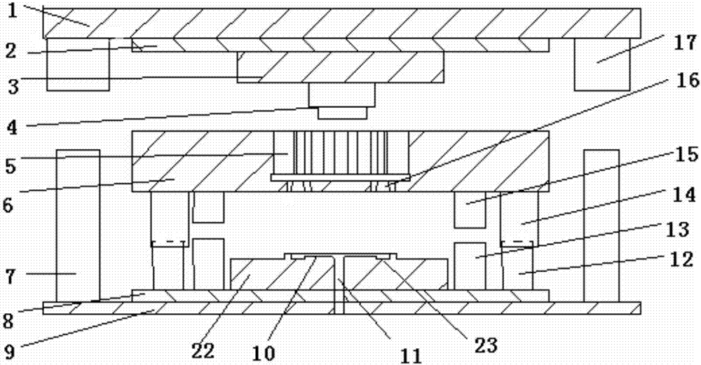
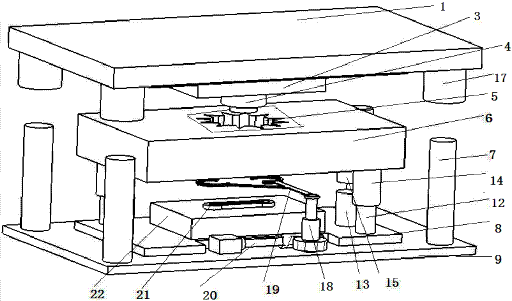
[0002]With the development of society, automobiles have already become the first means of travel for people to travel, and the demand is gradually increasing. Therefore, the processing industry of its auto parts is also facing The bigger challenge is that due to the increase in demand and the improvement of people's requirements, it is necessary not only to improve production efficiency but also to ensure better quality in the production process of auto parts. For the foundry industry that produces auto parts, for different parts The structure needs to be specially designed for its special mold. The existing die-casting molds generally only have the mold opening and closing of the convex mold and the concave mold part. For the mold fed from the bottom, the structure is single, and the waste of the gate part is not easy to take out, it is easy Cause damage to the contact part. In view of this situation, the present invention proposes a new type of die-casting mold for automobile parts. Through the improvement of the existing mold structure, for castings with symmetrical structures, the automatic separation of castings and waste materials is guaranteed during demoulding. , and the separation plane is relatively smooth, the waste can be automatically released from the mold, which saves labor, improves work efficiency, and ensures the safety of staff

Method used


Image

  • Novel die-casting die for automobile part
  • Novel die-casting die for automobile part
  • Novel die-casting die for automobile part

Examples


Embodiment Construction

[0032] It should be noted that, in the case of no conflict, the embodiments of the present invention and the features in the embodiments can be combined with each other.

[0033]In describing the present invention, it should be understood that the terms "center", "longitudinal", "transverse", "upper", "lower", "front", "rear", "left", "right", " The orientations or positional relationships indicated by "vertical", "horizontal", "top", "bottom", "inner" and "outer" are based on the orientations or positional relationships shown in the drawings, and are only for the convenience of describing the present invention and Simplified descriptions, rather than indicating or implying that the device or element referred to must have a particular orientation, be constructed and operate in a particular orientation, and thus should not be construed as limiting the invention. In addition, the terms "first", "second", etc. are used for descriptive purposes only, and should not be interpreted ...


PUM


Abstract

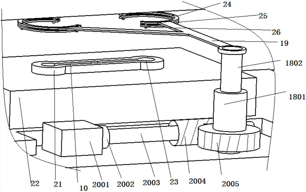
The invention provides a novel die-casting die for an automobile part. The novel die-casting die comprises an upper die seat, an upper cushion plate, a male die fixing plate, a female die fixing plate, a fixing plate, a lower cushion plate and a lower die seat which are sequentially arranged from top to bottom. Guide columns and guide sleeves are evenly distributed between the upper die seat and the lower die seat. Symmetric conic through holes are formed in the position, corresponding to a female die, of the bottom of the female die fixing plate. Grooves corresponding to the conic through holes are formed in the upper surface of the fixing plate. The two grooves are connected through an arc trench to form a sub-runner. The female die fixing plate and the fixing plate are in sliding fit connection through small guide columns and small guide sleeves. According to the novel die-casting die for the automobile part, for a casting with a symmetric structure, it is guaranteed that the separating face during automatic separation of the casting and waste is smooth during demolding, a workpiece cannot be damaged, material waste is reduced, and renovation on the automobile part after die casting is low; the workload of workers is saved; and the work efficiency is improved.

Description

technical field [0001] The invention belongs to the field of die-casting molds, in particular to a novel die-casting mold for automobile parts. Background technique [0002] With the development of society, automobiles have already become the first travel tool for people to travel, and the demand is gradually increasing. Therefore, the processing industry of its auto parts is also facing greater challenges. Due to the increase in demand and the improvement of people's requirements , in the production process of auto parts, it is necessary not only to improve production efficiency but also to ensure better quality. For the foundry industry that produces auto parts, it is necessary to design special molds for different parts structures. Existing die-casting molds Generally, only the mold opening and mold closing of the male mold and the concave mold part are performed. For the mold fed from the bottom, the structure is single, and the waste of the gate part is not easy to take...

Claims


Application Information

Patent Timeline
IPC IPC(8): B22D17/22
CPCB22D17/22B22D17/2236B22D17/229Y02P70/10
Inventor 张海宽于大宽
Owner 大川精工(朝阳)有限公司
Learn More