Detection method for geometrical errors of rotation shaft of five-axis numerical control machine tool

A technology of numerical control machine tools and detection methods, applied in the direction of measuring/indicating equipment, metal processing machinery parts, metal processing equipment, etc., can solve the problems of long measurement period, high cost of measurement equipment, high cost of laser target balls, etc., and solve geometric errors The identification and detection, the machine tool running trajectory requirements are simple, and the effect of avoiding other axis linkage errors

Active Publication Date: 2017-09-22
DALIAN UNIV OF TECH
View PDF11 Cites 33 Cited by
  • Summary
  • Abstract
  • Description
  • Claims
  • Application Information

AI Technical Summary

Problems solved by technology

Fu Jianzhong of Zhejiang University, the patent number is: CN103878641 A "A general-purpose identification method for the geometric error of the rotary axis of a five-axis CNC machine tool" established a measurement model for the geometric error of the rotary axis of a five-axis CNC machine tool by using a ballbar measuring device, and identified two rotation axes 16 geometric errors of the rotating shaft, but this method requires 3 measurement modes of the ballbar, and the measurement accuracy is affected by the installation accuracy of the ballbar, and the measurement cycle is longer
Liu Xinjun of Tsinghua University, the patent number is: CN 105479268 A "Recognition method for geometric error of swing axis of five-axis CNC machine tool based on RTCP" invented a general measurement method for geometric error of swing axis of five-axis

Method used


Image

  • Detection method for geometrical errors of rotation shaft of five-axis numerical control machine tool
  • Detection method for geometrical errors of rotation shaft of five-axis numerical control machine tool
  • Detection method for geometrical errors of rotation shaft of five-axis numerical control machine tool

Examples


Embodiment Construction

[0040] The specific embodiments of the present invention will be described in detail below in conjunction with the technical solutions and accompanying drawings.

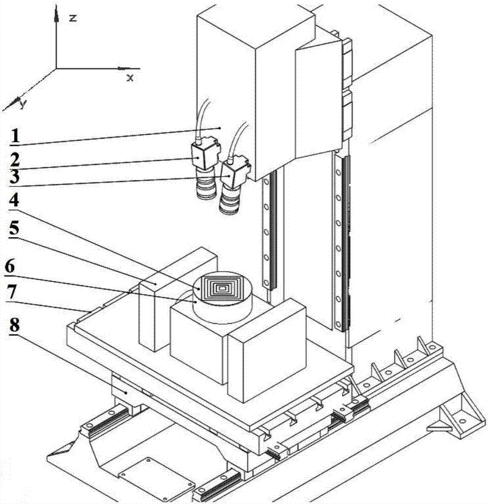
[0041] The present invention uses a binocular camera to measure the C-axis geometric error of the machine tool, such as figure 1 As shown, the left camera 2 and the right camera 3 are installed on the Z-axis 1 of the machine tool, and the "Hui"-shaped target is attached to the C-axis 6 of the machine tool. The binocular camera is used to collect the three-dimensional coordinates of its corners to characterize the movement characteristics of the C-axis of the machine tool. First adjust the left and right cameras to form a certain angle, the range is between 30°-60°, so that the common field of view is suitable, and the selected public field of view of the present invention is 200mm × 200mm.

[0042] The specific steps of the detection method are as follows:

[0043] The first step is to build a binocular measurement...


PUM


Abstract

The invention discloses a detection method for geometrical errors of a rotation shaft of a five-axis numerical control machine tool, belongs to the technical field of machine tool precision detection, and relates to a detection and identification method for the geometrical errors of the rotation shaft of the five-axis numerical control machine tool. The detection method comprises the steps that image information of a concentric target are collected by a binocular camera and used for representing the actual movement information of the rotation shaft, the three-dimensional coordinate information of a feature point is acquired finally through camera calibration and image processing, and the movement track represents the space movement track of one point on the rotation shaft; and through combination of a multi-body system theory of the machine tool and a subcoordinate transformation theory of the machine tool, the errors PIGE having no relation to the position of the rotation shaft and the errors PDGE having a relation to the movement position of the rotation shaft are identified and measured. The method effectively achieves detection and identification of the geometrical errors of the rotation shaft of the machine tool, the measurement process is simple and fast, and the measurement efficiency is high. The requirements for the operation track of the machine tool are simple in the measurement process, cooperation with other shafts is not needed, and other shaft linkage errors are avoided.

Description

technical field [0001] The invention belongs to the field of geometric error detection of machine tools, and relates to a geometric error detection method of a rotary axis of a five-axis numerically controlled machine tool. Background technique [0002] With the continuous advancement of manufacturing technology, the demand for mechanical parts with complex geometry and high precision has increased dramatically. Compared with traditional three-axis machine tools, five-axis machine tools have three linear motion axes and two rotary motion axes. The ability to provide feed in two directions of rotation makes the machining process of the machine tool more flexible, so more and more five-axis machine tools are applied to the manufacturing industry. In the research of five-axis CNC machine tools, how to improve their machining accuracy has become the main focus . The geometric error of the machine tool can well reflect the processing quality of the parts, and the rapid and accur...

Claims


Application Information

Patent Timeline
IPC IPC(8): B23Q17/24
CPCB23Q17/2452
Inventor 刘巍李辉李肖潘翼严洪悦
Owner DALIAN UNIV OF TECH
Why Eureka
Try Eureka