Vertical takeoff and landing fixed wing unmanned aerial vehicle with variable pitch propellers

A vertical take-off and landing, propeller technology, applied in the direction of vertical take-off and landing aircraft, unmanned aircraft, landing gear, etc., can solve the problems of poor maneuverability, low flight speed, and the inability to meet the rapid flight of drones, etc., to achieve reduction Dependence on the runway of the venue and the effect of good stability

Inactive Publication Date: 2017-09-22
SHENYANG AEROSPACE UNIVERSITY
View PDF5 Cites 10 Cited by
  • Summary
  • Abstract
  • Description
  • Claims
  • Application Information

AI Technical Summary

Problems solved by technology

[0003] Most of the existing UAVs have the following problems: 1. Most of the fixed-wing UAVs need to use the runway to take off and land. Therefore, the fixed-wing UAVs have relatively high requirements for the venue; Perform vertical take-off and landing, but the flight speed is low, which cannot meet the conditions for the rapid flight of drones and has poor maneuverability

Method used


Image

  • Vertical takeoff and landing fixed wing unmanned aerial vehicle with variable pitch propellers
  • Vertical takeoff and landing fixed wing unmanned aerial vehicle with variable pitch propellers
  • Vertical takeoff and landing fixed wing unmanned aerial vehicle with variable pitch propellers

Examples


Embodiment Construction

[0021] The present invention will be described in further detail below in conjunction with embodiment.

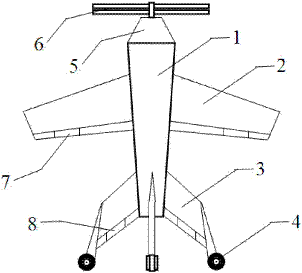
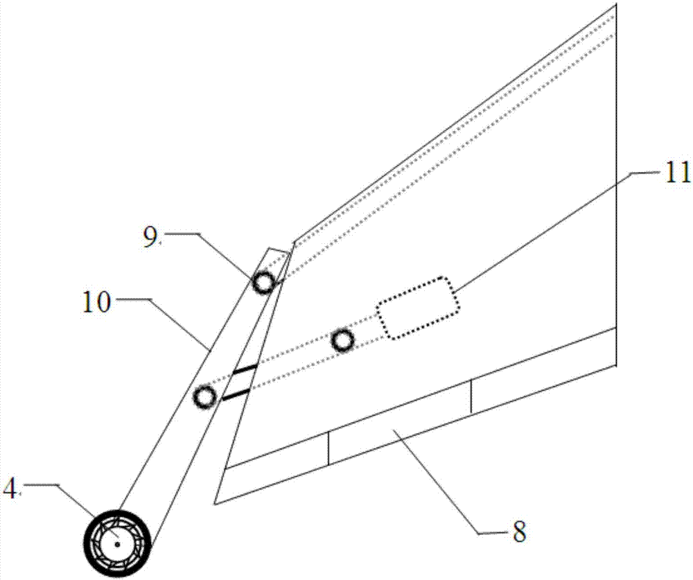
[0022] according to figure 1 , figure 2 with Figure 4 As shown, a vertical take-off and landing fixed-wing unmanned aerial vehicle with a variable torque propeller comprises a fuselage 1, and the middle and tail of the fuselage 1 are respectively equipped with a wing 2 and an empennage 3, and the empennage 3 has at least three The angle between two adjacent empennages 3 is less than 180 degrees, and the empennages 3 distributed on both sides of the fuselage are symmetrically arranged, and an aileron 7 is hinged at the rear edge of the wing 2, and the empennage 3 There is a tail rudder 8 hinged on it. During the flight, the roll of the UAV is controlled by adjusting the aileron 7, and the pitch and yaw of the UAV are controlled by the tail rudder 8. The engine 5 is installed at the top, and two sets of variable torque propellers 6 are installed on the output shaft of th...


PUM


Abstract

The invention relates to a vertical takeoff and landing fixed wing unmanned aerial vehicle with variable pitch propellers. The vertical takeoff and landing fixed wing unmanned aerial vehicle comprises an unmanned aerial vehicle body, wherein wings are separately and fixedly mounted at the middle part of the unmanned aerial vehicle body, and tail wings are separately and fixedly mounted at the tail of the unmanned aerial vehicle body; an engine is mounted at the head of the unmanned aerial vehicle body; two sets of variable pitch propellers are mounted on an output shaft of the engine; when the unmanned aerial vehicle runs, the rotating directions of the two sets of the variable pitch propellers are opposite; each buffer lifting mechanism is arranged on the corresponding tail wing, and comprises a connecting rod, a buffering device and a roller, wherein one end of each connecting rod is hinged to the corresponding tail wing, and the other end of the connecting rod is hinged to the corresponding roller; the middle part of each connecting rod is hinged to the corresponding buffering device which is fixedly mounted in the corresponding tail wing; vertical takeoff, landing and parking are performed by the buffer lifting mechanisms, so that on one hand, the vertical takeoff and landing fixed wing unmanned aerial vehicle has the flight speed of a fixed wing unmanned aerial vehicle, and on the other hand, can perform vertical takeoff, landing and hanging like a rotor unmanned aerial vehicle, and the dependency of the unmanned aerial vehicle on site runways is greatly reduced; and rollers are separately arranged at the tail wings of the unmanned aerial vehicle, and in the flight process, the rollers are driven by an air current to rotate at a high speed, so that in the flight process, the attitude of the unmanned aerial vehicle has better stability.

Description

Technical field: [0001] The invention relates to the technical field of unmanned aerial vehicles, in particular to a vertical take-off and landing fixed-wing unmanned aerial vehicle with variable torque propellers. Background technique: [0002] With the changes of the times, although the popularity of manned aircraft has not decreased, it has gradually exposed many disadvantages. For example, the cost of the aircraft is too high, and the crash of the aircraft threatens the life of the pilot, which makes the safety and technical requirements of manned aircraft continue to increase. Thereby, the cost of the aircraft is also continuously increased. In order to reduce the cost of manned aircraft and adapt to the development needs of modern warfare and society, countries have successively developed an unmanned aircraft, referred to as UAV. In recent years, in global local wars, the military has used drones to attack terrorists, conduct reconnaissance and surveys on battlefields...

Claims


Application Information

Patent Timeline
Patent Type & Authority Applications(China)
IPC IPC(8): B64C29/00B64C25/34B64C25/62B64C17/00
CPCB64C17/00B64C25/34B64C25/62B64C29/0025B64U10/25B64U70/80B64U30/20
Inventor 徐光延孟亭磊陈侠
Owner SHENYANG AEROSPACE UNIVERSITY
Why Eureka
Try Eureka