Ampoule bottle feeding platform
A feeding platform and ampoule bottle technology, applied in the direction of conveyors, conveyor objects, transportation and packaging, etc., can solve the problem of easy falling off of the bottle body, and achieve the effects of avoiding the falling off of the bottle body, convenient adjustment, and convenient positioning
- Summary
- Abstract
- Description
- Claims
- Application Information
AI Technical Summary
Problems solved by technology
Method used
Image

Examples
Embodiment 1
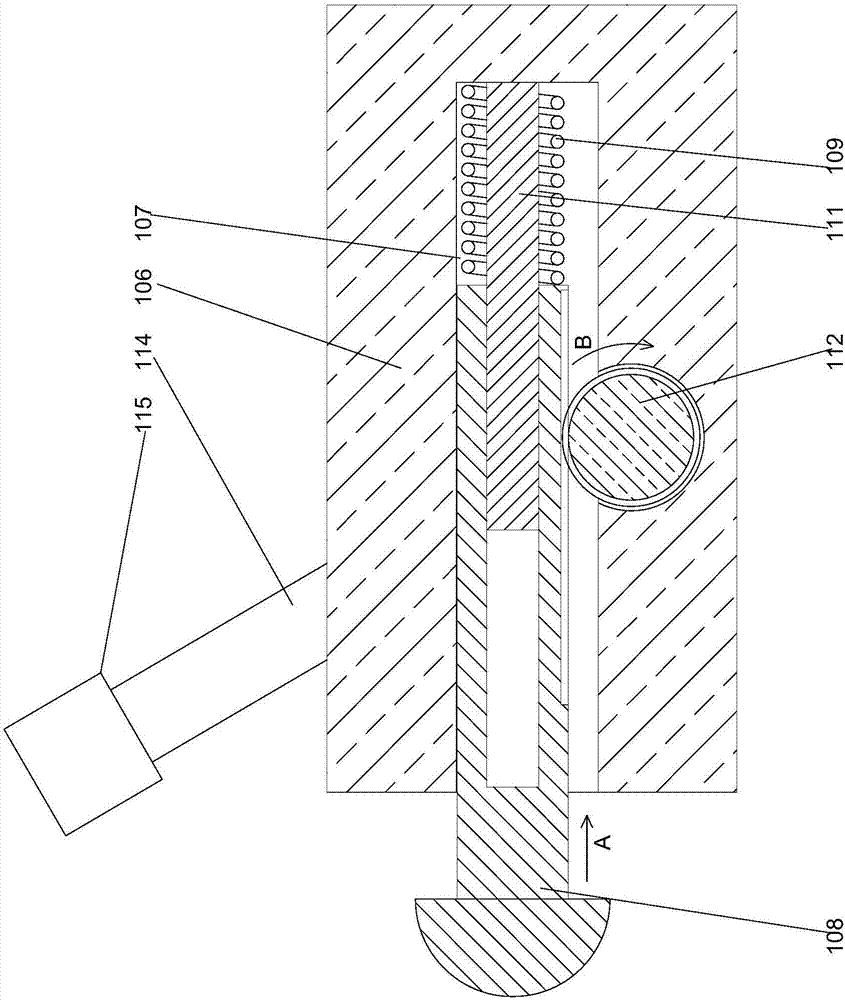
[0028] In order to facilitate the positioning of the bottle body from the side, in this embodiment, a preferred structure for restricting the movement of the bottle body from the side is disclosed. A positioning post 111 is provided inside the semi-through hole 107, and the end of the positioning post 111 is inserted into the inside of the counterbore, under the end of the locking block 108 close to the spring 109 Teeth are arranged on the end face, and a rotating shaft 112 is arranged inside the lower positioning block 106, and one end of the rotating shaft 112 extends into the inner side of the half-through hole 107, and a rotating shaft 112 is provided on the rotating shaft 112 to match the described The teeth are meshed with each other, and a bar-shaped hole 113 is provided on the upper end surface of the middle part of the lower positioning block 106, and a pressing rod 114 is arranged on the described rotating shaft 112, and the described pressing rod 114 is far away from...
Embodiment 2
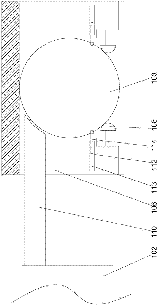
[0032] In order to increase the relative friction between the pressing rod and the bottle body, in this embodiment, on the basis of Embodiment 1, preferably, a rubber pad 115 is provided at the end of the pressing rod 114 away from the rotating shaft 112 The end surface of the rubber pad 115 facing the inner side of the locking groove 105 is inwardly recessed to form a concave structure. In this embodiment, the concave structure can be attached to the side wall of the bottle body, and the contact area between the rubber pad and the bottle body is increased, so that the bottle body cannot move to the outside under the action of the rubber pad, which can help To improve the stability of the bottle body, while avoiding the pressure bar from wearing the surface of the bottle body.
[0033] Further preferably, in this embodiment, the rubber pad 115 has a hollow cylindrical structure, and the concave structures are at least three in a ring-shaped array along the outer wall of the ru...
Embodiment 3
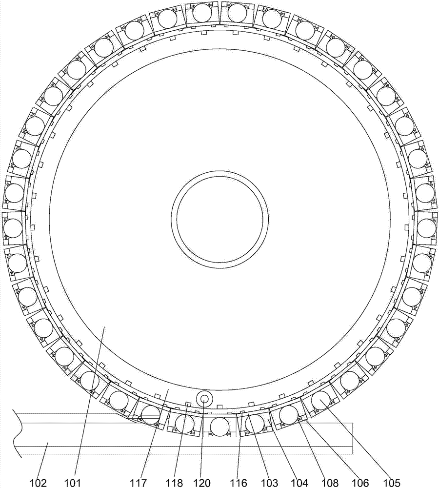
[0035] In this embodiment, in order to facilitate the bottle body to move out from the inside of the bottle body when it reaches the stopper position, a structure for pushing the bottle body is set on the feeding platform. Preferably, on the feeding platform 101 An annular groove 117 is provided on the end face, and a through hole communicating with the groove 117 corresponding to the position of the bottle support block 103 is provided on the side wall of the feeding platform 101. A sliding rod 118 is provided inside the through hole, and a support 120 is provided on the delivery trough 102, and the end of the support 120 away from the delivery trough 102 is bent toward the direction of the groove 117 and extends into Inside the groove 117, a roller is provided at the end of the bracket 120 away from the conveying groove 102, and the end of the sliding rod 118 close to the groove 117 is bent towards the bottom of the groove 117, The spring 109 connecting the groove 117 and th...
PUM
 Abstract
Description
Claims
Application Information
 - R&D Engineer
- R&D Manager
- IP Professional
- Industry Leading Data Capabilities
- Powerful AI technology
- Patent DNA Extraction
Browse by: Latest US Patents, China's latest patents, Technical Efficacy Thesaurus, Application Domain, Technology Topic.
© 2024 PatSnap. All rights reserved.Legal|Privacy policy|Modern Slavery Act Transparency Statement|Sitemap