Precision core drilling machine

A technology of precision drilling and coring machine, which is used in earth-moving drilling, mechanical equipment, extraction of undisturbed core devices, etc. Strong vibration ability, stable gear transmission, and the effect of increasing service life

Active Publication Date: 2017-09-22
杨婷
View PDF5 Cites 6 Cited by
  • Summary
  • Abstract
  • Description
  • Claims
  • Application Information

AI Technical Summary

Problems solved by technology

One is electric, and the other is engine. It is very inconvenient to use electricity in field construction, so the electric drilling and coring machine is very inconvenient to use, especially in long-distance highway construction.
[0003] However, whether it is an electric drill coring machine or an engine drill coring machine, most of them use belt transmission for power transmission at present. Belt transmission has many disadvantages: (1) When the belt is working, due to the tension on both sides of the pulley The difference and the corresponding deformation form elastic sliding through the difference, resulting in the speed loss of the pulley and the driven wheel
(2) When overloaded, it will cause slipping, which will make the movement of the belt in an unstable state, the efficiency will drop sharply, and the wear will increase, which will seriously affect the life of the belt.
(3) The vibration of the belt drive is large and unstable during use, which causes the hollow drill to be unstable when rotating and prone to deviation, which greatly reduces the service life of the hollow drill when drilling, and the obtained sample core is irregular

Method used


Image

  • Precision core drilling machine
  • Precision core drilling machine
  • Precision core drilling machine

Examples


Embodiment Construction

[0031] Below in conjunction with specific embodiment, further illustrate the present invention. It should be understood that these examples are only used to illustrate the present invention and are not intended to limit the scope of the present invention. In addition, it should be understood that after reading the content taught by the present invention, those skilled in the art may make various changes or modifications to the present invention, and these equivalent forms also fall within the scope defined in the present application.

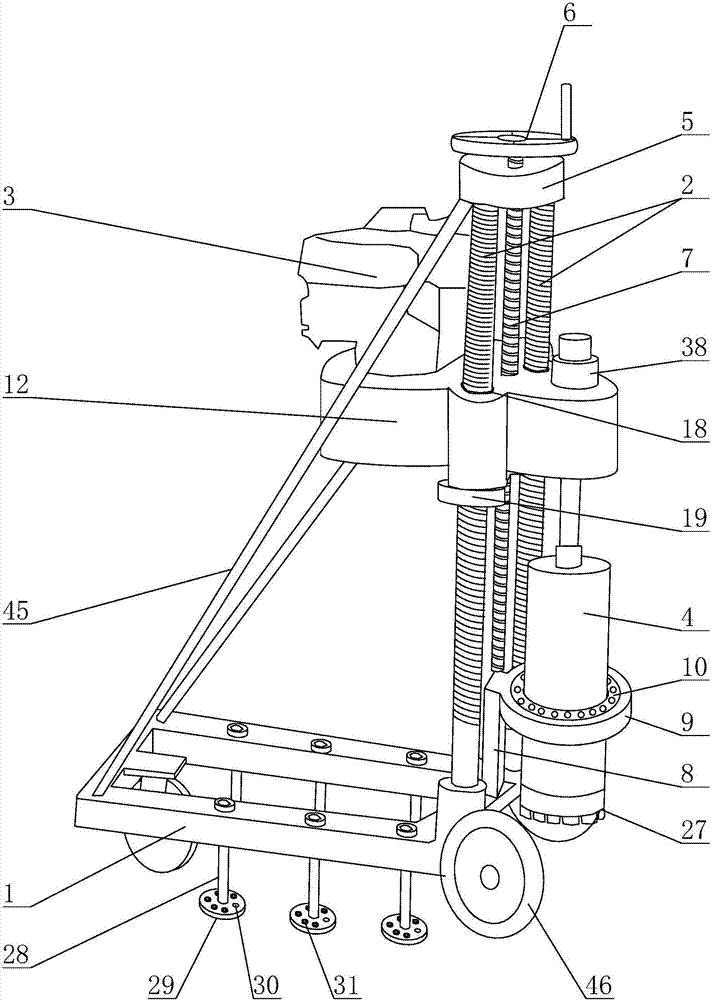
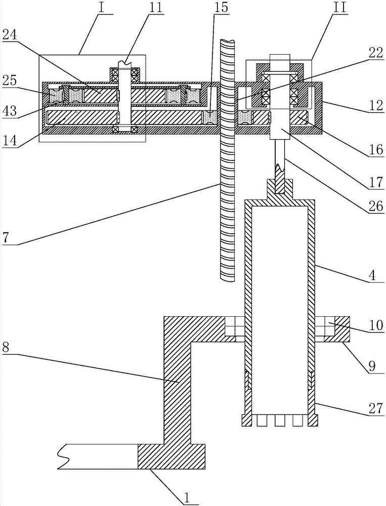
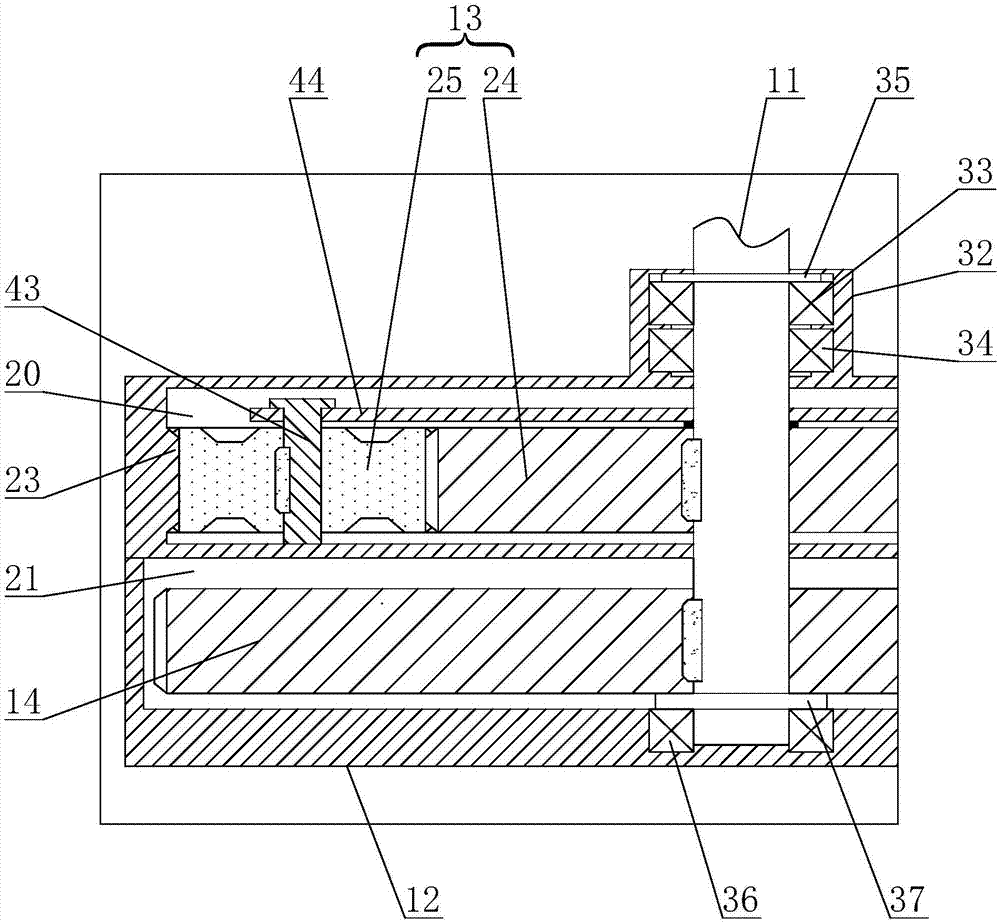
[0032]The present invention is a precision drilling and coring machine. The main structure includes a base 1, a threaded rod 2, an anti-drilling device, a transmission assembly, a vertical engine 3, a hollow drill 4, a top seat 5, and a rotating hand wheel. 6 and lead screw 7, said threaded rod 2 is provided with 2, respectively arranged on both sides of the width direction of base 1, the bottom of said threaded rod 2 is connected with base 1, a...


PUM


Abstract

The invention discloses a precision core drilling machine. The machine includes a base, a threaded rod, an anti-deviation device, an actuator assembly, a vertical engine, a hollow drill, a top base, a rotating hand wheel and a leading screw, wherein the actuator assembly is composed of a driving shaft, an outer shell body, a planetary gear train, a big sun gear, a transition gear, a tail end gear and a driven shaft; the side wall of a planetary gear groove is provided with annular gears, and the planetary gear train includes a small sun gear and small planetary gears; the driving shaft is successively connected to the small sun gear and the big sun gear in a key joint mode; one end of the transition gear is meshed with the big sun gear, and the other end of the transition gear is meshed with the tail end gear; the leading screw is connected to the internal of a nut sleeve, the driven shaft is connected to the tail end gear in a key joint mode, and the bottom of the driven shaft is connected to the hollow drill. The precision core drilling machine has the advantages that a series of deficiencies in the adoption of belt transition are abandoned, and transmission is much stabler during drilling; the rotation of the hollow drill is much stabler, deviation does not occur easily, and obtained core samples are more precision and uniform.

Description

technical field [0001] The invention relates to the field of drilling and coring machines, in particular to a precision drilling and coring machine. Background technique [0002] Current drilling and coring machines are divided into two categories. One type is electric, and the other type is engine. It is very inconvenient to use electricity in field construction, so the electric drilling and coring machine is very inconvenient to use, especially its shortcomings are more obvious in long-distance road construction. [0003] However, whether it is an electric drill coring machine or an engine drill coring machine, most of them use belt transmission for power transmission at present. Belt transmission has many disadvantages: (1) When the belt is working, due to the tension on both sides of the pulley The difference and the corresponding deformation form elastic sliding through the difference, resulting in the speed loss of the pulley and the driven wheel. (2) When overloaded...

Claims


Application Information

Patent Timeline
Patent Type & Authority Applications(China)
IPC IPC(8): E21B25/00F16H1/28
CPCE21B25/00F16H1/28
Inventor 温晓妮
Owner 杨婷
Why Eureka
Try Eureka