
Combination structure of circuit board and fan frame

A circuit board and fan technology, which is applied in the field of combined structure of the circuit board and fan frame, can solve problems such as tilting, reduced circuit layout space of the printed circuit board 12, damage, etc.

Active Publication Date: 2019-11-22
ASIA VITAL COMPONENTS SHENZHEN CO LTD
View PDF6 Cites 0 Cited by
  • Summary
  • Abstract
  • Description
  • Claims
  • Application Information

AI Technical Summary

Problems solved by technology

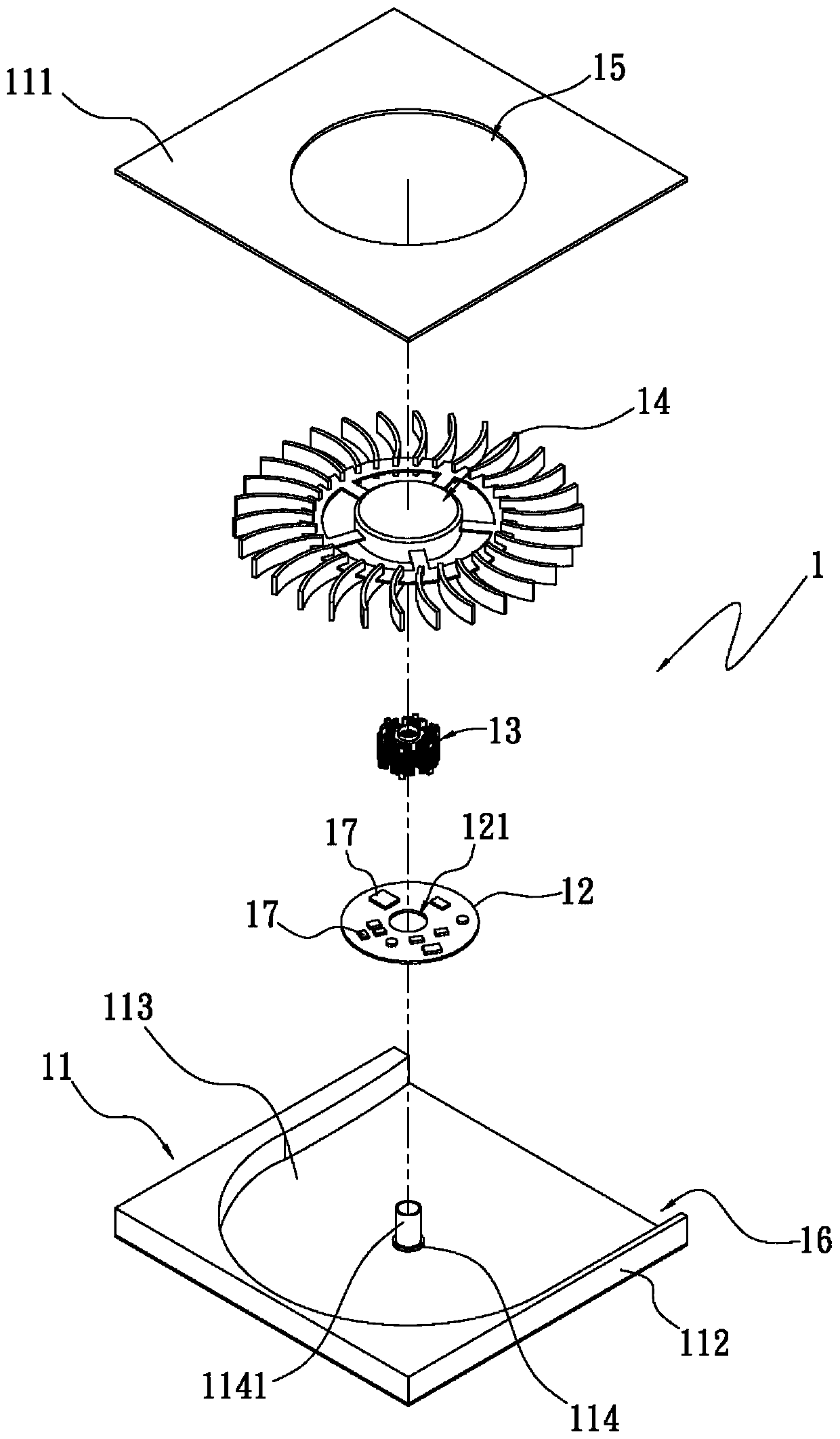
[0004] And because the printed circuit board 12 must be provided with the opening corresponding to the shaft cylinder 1141 in advance, so the circuit layout space of the printed circuit board 12 is reduced.
In addition, the known printed circuit board 12 is arranged on the inner side of the bottom plate 113 in the fan frame 11, mainly through a pressing mold (not shown in the figure) to the printed circuit board 12 that has a plurality of electronic components 17 on it. One side is pressed down, so that the printed circuit board 12 can be attached on the inner side of the bottom plate 113 in the fan frame 11, but because the electronic components 17 are not pressure-resistant and easily damaged, it is often used on the printed circuit board. The electronic components 17 on 12 are damaged by pressing, and the height and size of each electronic component 17 are different, so the pressing mold will easily cause uneven pressing force when pressing down, so that it is easy to cause the electronic components to be damaged. 17 Damage and the problem that the printed circuit board 12 is not easy to attach and lifts up
In addition, a space needs to be reserved on the inner side of the bottom plate 113 adjacent to the shaft cylinder 1141 in the fan frame 11 for the printed circuit board 12 to be placed, resulting in the problem that the printed circuit board 12 occupies the space in the fan frame 11

Method used


Image

  • Combination structure of circuit board and fan frame
  • Combination structure of circuit board and fan frame
  • Combination structure of circuit board and fan frame

Examples


Embodiment Construction

[0059] The above-mentioned purpose of the present invention and its structural and functional characteristics will be described based on the preferred embodiments of the accompanying drawings.

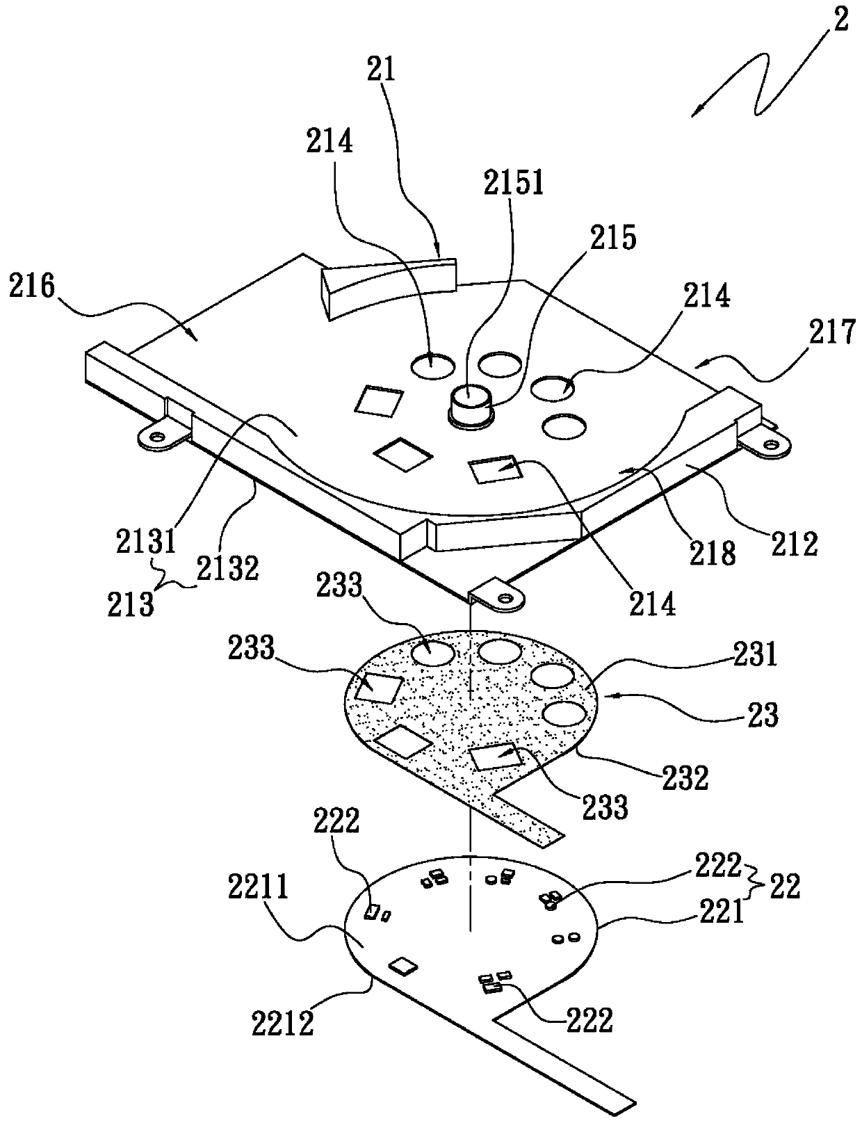
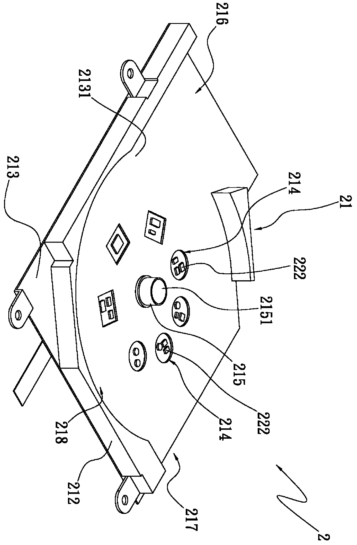
[0060] A combination structure of a circuit board and a fan frame in the present invention, please refer to figure 2 , 3 , the exploded and combined three-dimensional schematic diagram of the first embodiment of the present invention, supplemented by reference Figure 4 , 5A, 5B. The combined structure 2 of the circuit board and the fan frame is applied to a fan 3. The fan 3 is shown as a centrifugal fan in this embodiment, but it is not limited thereto. In actual implementation, the fan 3 can also be a shaft Flow fan or other fans. The fan 3 includes the above-mentioned circuit board and fan frame combination structure 2 and a fan wheel 31 with a plurality of blades 312. The circuit board and fan frame combination structure 2 includes a fan frame 21, a circuit board 22 and an adh...


PUM


Abstract

The invention provides a combined structure of a circuit board and a fan frame. The combined structure comprises the fan frame, the circuit board and a gluing piece, wherein a plurality of through holes are formed in the gluing piece, the fan frame comprises a bottom plate, a beam barrel which is arranged in the middle of the bottom plate and a plurality of holes which penetrate through the bottom plate, the bottom plate is provided with an upper surface and a lower surface, and the circuit board is glued on the lower surface of the bottom plate through the gluing piece, so that a plurality of electronic elements on the circuit board correspondingly penetrate through the through holes and the holes.

Description

【Technical field】 [0001] The invention relates to a combined structure of a circuit board and a fan frame, especially a circuit that can save space in the fan frame and increase the space for circuit layout of the circuit board, and can also avoid the problem of the circuit board warping Combination structure of board and fan frame. 【Background technique】 [0002] With the increasing development of the technology industry, known electronic devices such as desktop computers, notebook computers, smart phones, and tablet computers have been frequently used in daily life, and these electronic devices usually include fans for heat dissipation . [0003] See for example figure 1 , the known centrifugal fan 1 comprises a fan frame 11, a printed circuit board 12, a stator 13 and a fan wheel 14, the fan frame 11 has a top plate 111, a side plate 112, a bottom plate 113 and a shaft seat 114, The bottom of the side plate 112 is connected to the outside of the bottom plate 113, the t...

Claims


Application Information

Patent Timeline
Patent Type & Authority Patents(China)
IPC IPC(8): F04D27/00F04D29/64H05K7/14
CPCF04D27/00F04D29/644H05K7/14
Inventor 申猛
Owner ASIA VITAL COMPONENTS SHENZHEN CO LTD
Learn More