Light shading plate for low-beam module of automobile headlamp and automobile headlamp

A technology of automobile headlights and visors, which is applied in the direction of shading, components of lighting devices, light sources, etc., can solve the problems of insufficient light in the three areas of low beams, dazzling vehicle drivers, and low visibility of drivers, so as to improve driving safety and driving comfort, reduced dispersion, and increased irradiation distance

Pending Publication Date: 2017-09-22
HASCO VISION TECHNOLOGY CO LTD
View PDF12 Cites 7 Cited by
  • Summary
  • Abstract
  • Description
  • Claims
  • Application Information

AI Technical Summary

Problems solved by technology

[0004] In the headlights of automobiles, a visor is set in front of the low beam reflector to block the upward direct light when the lights are on, otherwise it will cause serious glare to the oncoming vehicle driver, and these scattered lights can be seen in rainy or foggy days. In the weather environment, a light curtain will be formed in front of the car, making the driver's visibility lower
[0005] The low beam of the car headlights is asymmetrical, that is, the light shape distribution (formed on the front light distribution screen) has an obvious light and dark cut-off line, and the low beam lights pass through the light and dark cut-off line to make the driving of pedestrians and oncoming vehicles To avoid glare or discomfort, the cut-off line of low light and dark light of the low beam module or integrated far and low beam module of most automobile headlights on the market currently passes through the shading plate located at the focal plane of the lens (similar to figure 1 ) to form a shading light pattern, but this simple vertical shading of the light path not only causes a large loss of energy of the light source, but also makes the light in the three areas of the low beam insufficient, making it difficult to meet the regulatory requirements

Method used


Image

  • Light shading plate for low-beam module of automobile headlamp and automobile headlamp
  • Light shading plate for low-beam module of automobile headlamp and automobile headlamp
  • Light shading plate for low-beam module of automobile headlamp and automobile headlamp

Examples


Embodiment Construction

[0030] The present invention will be described in further detail below in conjunction with the accompanying drawings and specific embodiments.

[0031] Example of visor:

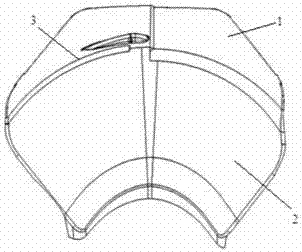
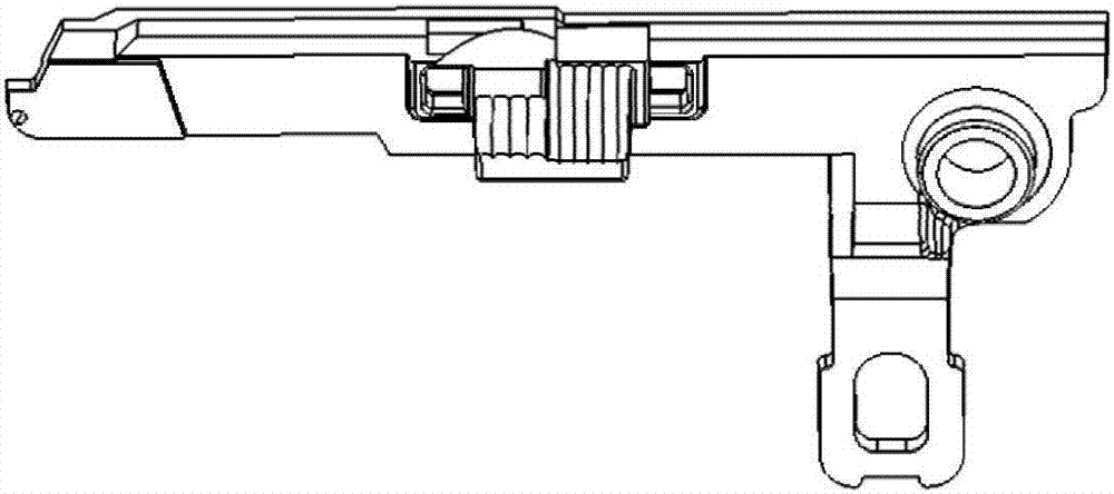
[0032] Such as figure 2 , the shading plate of the present invention comprises two inclined first shading sheets 1 and second shading sheets 2, wherein one end boundary of the first shading sheet intersects with the upper boundary of the second shading sheet, and the first shading sheet The intersecting part of the first light-blocking sheet and the second light-blocking sheet is the cut-off line 3, wherein the first light-blocking sheet is located on the side close to the light source, and the front of the first light-blocking sheet is aluminum-plated to form a reflective surface for reflecting light. The reflective surface is equivalent to image 3 The cut-off line of the single-disk shading sheet shown is a reflective surface formed by stretching toward the light source side at a set angle. The reflec...


PUM


Abstract

The invention relates to a light shading plate for a low-beam module of an automobile headlamp and the automobile headlamp. The light shading plate comprises a first light shading piece and a second light shading piece which are inclined; the upper boundary of the first light shading piece intersects with the upper boundary of the second light shading piece; a cut-off line is formed at the parts where the first light shading piece intersects with the second light shading piece; the first light shading piece is located on one side close to a light source; the cut-off line stretches at the set angle towards the light source side to form the first light shading piece; and the front surface of the first light shading piece is a light reflecting surface and is used for reflecting light. Part of the light emitted by the light source irradiates the light reflecting surface, is reflected by the light reflecting surface and then penetrates through a lens, so that the energy loss is reduced. With the light shading plate and the automobile headlamp, the utilization efficiency for the energy of the light source is higher, meanwhile, the driving comfort and safety of a driver are improved, and the problems that a lot of energy of light sources is lost, low-beam three-zone parts are insufficient in light and regulation requirements are difficult to meet due to existing light shading plates are solved.

Description

technical field [0001] The invention relates to an automobile lamp, in particular to a light-shielding plate used for a low beam module of an automobile headlamp and the automobile headlamp. Background technique [0002] With the development of automotive electronics and the improvement of customers' requirements for the appearance of automobiles, motor vehicle lighting regulations have put forward higher requirements for the light shape of automobile headlights. The design content that needs to be considered in the automotive lighting manufacturing industry has become more and more difficult. [0003] Among them, the headlight regulations set an upper limit on the brightness of certain lighting areas, and at the same time put forward requirements for the light shape of the car headlights, requiring a certain illuminance in the dark area of ​​the headlight shape of the car. Most require a certain illuminance in the dark area of ​​the headlight shape of the car, in order to ...

Claims


Application Information

Patent Timeline
Patent Type & Authority Applications(China)
IPC IPC(8): F21S8/10F21V1/12F21V7/00F21W101/10
CPCF21V1/12F21V7/00
Inventor 李云舟
Owner HASCO VISION TECHNOLOGY CO LTD
Why Eureka
Try Eureka