A mechanical microseismic source and monitoring system and method of use

A technology of microseismic monitoring and seismic source, which is applied in seismology, measuring devices, geophysical measurement, etc., can solve the problems of high manpower, material and financial resources, low manual picking accuracy, mixed blasting events, etc., and achieve low seismic source frequency and use The process is safe and fast, with little impact on the effect

Active Publication Date: 2019-01-25
CENT SOUTH UNIV
View PDF5 Cites 0 Cited by
  • Summary
  • Abstract
  • Description
  • Claims
  • Application Information

AI Technical Summary

Problems solved by technology

[0003] The traditional microseismic monitoring process uses blasting as the seismic source for monitoring. In order to analyze the impact of blasting operations on the stability of mine roadways and chambers, the monitored area is mostly close to the blasting site, and a large number of blasting events are mixed in the monitored data. At present, there is no method to automatically and accurately identify blasting events and microseismic events. Most of them need to be picked up manually by people. This process not only consumes a lot of manpower, material and financial resources, but also takes a long time.
Most importantly, the accuracy of manual picking is not high, which has great disadvantages in the process of guiding mine production

Method used


Image

  • A mechanical microseismic source and monitoring system and method of use
  • A mechanical microseismic source and monitoring system and method of use

Examples


Embodiment 1

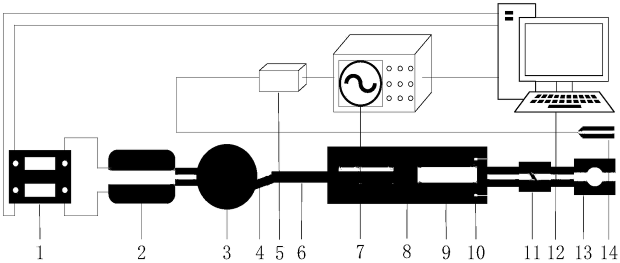
[0040]A mechanical microseismic source, the microseismic source includes a driving power, a pressure accumulator cavity, a safety valve, and an energy projecting head; the driving power includes a motor (2), a flywheel (3), and a crankshaft (4); the pressure accumulating The cavity includes a piston (8) and a cylinder (9); the motor (2) is electrically connected to the electronic switch (1), and the electronic switch (1) controls the on-off of the power supply of the motor (2), and the output of the motor (2) The flywheel (3) is driven, and the flywheel (3) is connected to one end of the crankshaft (4); the other end of the crankshaft (4) is connected to the connecting rod (6) arranged on the piston (8), and the driving piston (8) is connected to the cylinder ( 9) reciprocating motion; on the cylinder (9), there is also 1 air outlet and 2 air inlets; the air outlet is connected with a safety valve (11) and an energy shooter (13) in sequence; the 2 Air intake valves (10) are re...

Embodiment 2

[0043] A mechanical microseismic source, the difference from Embodiment 1 is:

[0044] An electronic switch (1) is connected to three driving powers at the same time, and a network is formed to realize simultaneous triggering of multiple seismic sources; the driving power is consistent with the number of pressure storage chambers.

Embodiment 3

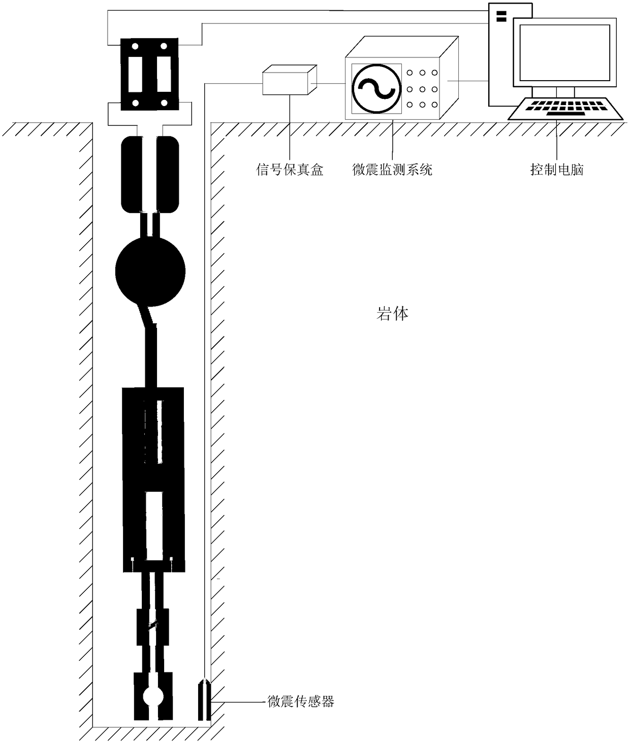
[0046] A microseismic monitoring system comprising a mechanical microseismic source, comprising a microseismic source, a signal fidelity box (5), a microseismic signal monitoring device (7), a control computer (12), and a microseismic sensor (14), characterized in that: the microseismic source The electronic switch (1) is electrically connected to the control computer (12); one end of the microseismic signal monitoring device (7) is electrically connected to the control computer (12), and the other end is electrically connected to the signal preservation box (5) and the microseismic sensor (14) successively. Connected, the microseismic sensor (14) is arranged on the periphery of the energy-emitting head in the micro-seismic source, with an average distance of 50 meters from the energy-emitting head.


PUM


Abstract

The invention discloses a mechanical microseism source, and a microseism monitoring system and a using method thereof. The microseism source comprises a driving power unit, a pressure storage cavity, a safety valve and an energy emission head; and the microseism source is characterized in that a gas outlet of the pressure storage cavity is connected with the safety valve and the energy emission head successively, the pressure storage cavity is provided with gas inlets, each gas inlet is internally provided with a non-return valve, and the driving power unit controls the magnitude of the pressure in the pressure storage cavity. The microseism monitoring system comprises the microseism source, a signal fidelity box, a microseism signal monitoring device, a control computer and a microseism sensor; and the system is characterized in that an electronic switch of the microseism source is electrically connected with the control computer, one end of the microseism signal monitoring device is electrically connected with the control computer, and the other end of the microseism signal monitoring device is electrically connected with the signal fidelity box and the microseism sensor successively. According to the invention, the structure is simple, operation is convenient, the energy releasing magnitude and direction can be controlled, and networking is allowed; and the microseism source is low in frequency and cost and safe in use, and provides hardware equipment support for microseism monitoring.

Description

technical field [0001] The invention relates to a mechanical microseismic source, a monitoring system and a use method, and belongs to the technical field of rock mass microseismic monitoring. technical background [0002] With the gradual reduction of shallow resources, a large number of mines are developing to the deep underground. During the excavation process of roadways and chambers, the deep high ground stress is disturbed, causing the stress concentration and redistribution, resulting in an unstable state of the originally stable surrounding rock. The elastic potential energy accumulated in the rock mass is gradually or suddenly released in the form of seismic waves during the inelastic deformation of the rock mass (crack expansion, rock mass slippage, etc.), resulting in a series of microseismic events. The sudden and disorderly release of elastic potential energy often induces disasters such as fault slippage or rockburst, which seriously restricts the normal produ...

Claims


Application Information

Patent Timeline
Patent Type & Authority Patents(China)
IPC IPC(8): G01V1/133G01V1/00
CPCG01V1/00G01V1/133
Inventor 董陇军孙道元李夕兵
Owner CENT SOUTH UNIV
Why Eureka
Try Eureka