
Heat pump unit mobile server control system and method

A technology for mobile servers and heat pump units, applied in transmission systems, wireless communication services, database management systems, etc., can solve problems such as high data processing pressure, unrecognizable units, and high server performance requirements, so as to reduce server pressure and improve real-time sexual effect

Inactive Publication Date: 2017-09-22
GUANGDONG PHNIX ECO ENERGY SOLUTION
View PDF2 Cites 3 Cited by
  • Summary
  • Abstract
  • Description
  • Claims
  • Application Information

AI Technical Summary

Problems solved by technology

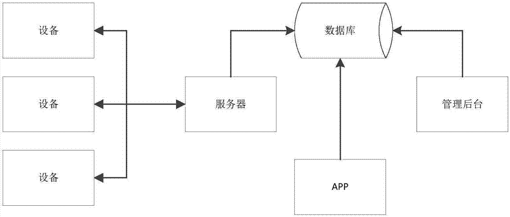
[0005] 1. Multiple devices are directly connected to the management background server. The server needs to collect, process and store the data concurrently transmitted by the devices into the database. The concurrent analysis and processing data has high requirements on the performance of the server, which may cause the existing management background server to paralysis;
[0006] 2. When the background management page on the server and the mobile terminal APP inquire about the relevant data of the unit, it is necessary to retrieve data from the database of the server, and often connect to the background management server to retrieve data, so that the data processing pressure is relatively high;
[0008] 4. The device data information is transmitted to the server through the WIFI module, and the management background identifies the device information through the MAC address of the WIFI module, but the after-sales engineer cannot identify the corresponding unit from the MAC address of the WIFI module;
[0009] 5. When the unit undergoes maintenance and the WIFI module is replaced, the MAC address of the original unit’s WIFI module will change, and one unit will have multiple pieces of data information in the management background server, which is inconvenient for background viewing and management

Method used


Image

  • Heat pump unit mobile server control system and method
  • Heat pump unit mobile server control system and method
  • Heat pump unit mobile server control system and method

Examples


Embodiment Construction

[0029] The specific embodiment of the present invention will be further described below in conjunction with accompanying drawing:

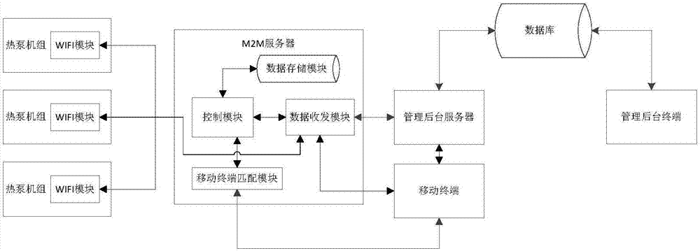
[0030] refer to figure 2 , a mobile server control system for a heat pump unit, comprising a management background terminal, a database, a management background server, a mobile terminal, an M2M server, and a WIFI module arranged on the heat pump unit, the M2M server comprising a control module, a data storage module, Mobile terminal matching module and data transceiving module, described control module is connected with data storage module and data transceiving module respectively, described control module is connected with mobile terminal through mobile terminal matching module, and described data transceiving module is connected with WIFI module, management background respectively The server is connected to the mobile terminal, the management background server is also connected to the mobile terminal, and both the management background server ...


PUM


Abstract

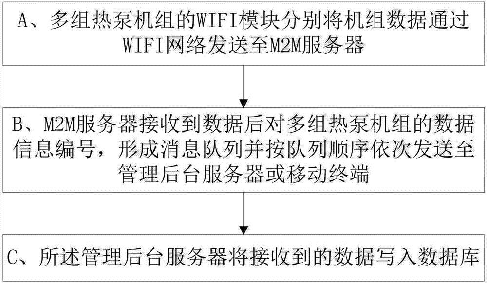
The present invention discloses a heat pump unit mobile server control system and method. The system comprises a management background terminal, a database, a management background server, a mobile terminal, an M2M server and a WIFI module arranged on the heat pump unit, wherein the M2M server comprises a control module, a data storage module, a mobile terminal matching module and a data transceiver module. According to the technical scheme of the present invention, by introducing the M2M server, the pressure that the management background server concurrently processes the data is solved, and data can be actively pushed to the management background server and the mobile terminal, so that the operation on the same database performed by a large number of links is avoided, the server pressure is reduced, and timeliness of mobile terminal operations is improved; in addition, by processing the unit bar code information, the unit is associated with the unit operation data information, so that, in particular, the phenomenon that the same unit has a plurality of data records simultaneously can be avoided; and the heat pump unit mobile server control system and method disclosed by the present invention can be widely applied to the field of heat pumps.

Description

technical field [0001] The invention relates to the field of heat pumps, in particular to a control system and method for a mobile server of a heat pump unit. Background technique [0002] In terms of thermal energy utilization technology, due to the increasingly complex systems of solar thermal utilization and air source heat pump units, the requirements for the control system are getting higher and higher. In addition, the traditional relay control has problems such as low control accuracy, which often leads to poor reliability of the control system. , Problem feedback is not timely. [0003] On the other hand, with the rapid development of wireless communication technology, the Internet of Things, with wireless communication network as the core and combined with application-side professional knowledge, has become a key trend in the development of many industries in the near future. Especially for industries or markets that need to meet the needs of decentralized, multi-p...

Claims


Application Information

Patent Timeline
IPC IPC(8): G06F17/30H04L29/08H04W4/00
CPCG06F16/22G06F16/25H04L67/12
Inventor 谢卓锐高翔刘远辉梁展悦张松标李守志
Owner GUANGDONG PHNIX ECO ENERGY SOLUTION
Learn More