Medium conveying device and medium conveying system

A medium conveying and medium technology, applied in coin accepting devices, instruments, handling coins or valuable banknotes, etc., can solve problems such as low strength of paper materials, failure of conveying structure, tearing, etc., to improve reliability and operation performance, avoid clogging, and protect integrity

Pending Publication Date: 2017-09-22
SHENZHEN YIHUA COMP +2
View PDF8 Cites 0 Cited by
  • Summary
  • Abstract
  • Description
  • Claims
  • Application Information

AI Technical Summary

Problems solved by technology

[0007] However, due to the low strength of paper materials, banknotes may be bent, worn or cracked due to folding during circulation in the market.
In the case of winding such banknotes, since only the middle part of the banknotes is subjected to the friction force of the conveyor belt, while the parts on both sides are in a suspended state, different areas of the banknote surface are subjected to uneven forces, and the bending and cracks of the banknotes usually It will appear on the edge of the banknote. If the curved or cracked part is just on both sides of the conveyor belt, the parts on both sides of the conveyor belt will sag due to gravity, making the parts on both sides of the banknote lower than the plane of the middle part. , which in turn causes the banknotes to be more severely curled or even torn during the process of winding them to the spool
[0008] In this case, the curled or torn part of the banknotes may not be normally wound onto the peripheral surface of the reel, but jammed near the conveyor belt and the reel, causing failure of the entire conveying structure

Method used


Image

  • Medium conveying device and medium conveying system
  • Medium conveying device and medium conveying system
  • Medium conveying device and medium conveying system

Examples


no. 1 example

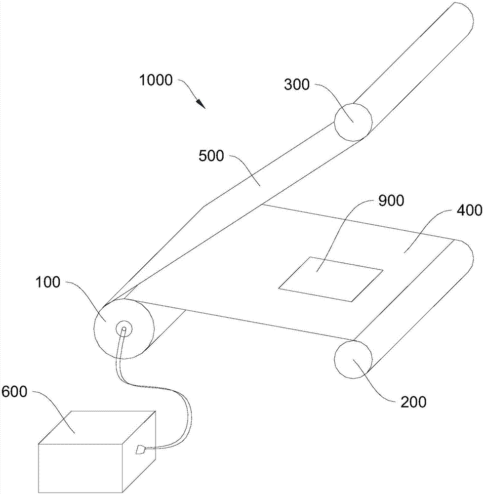
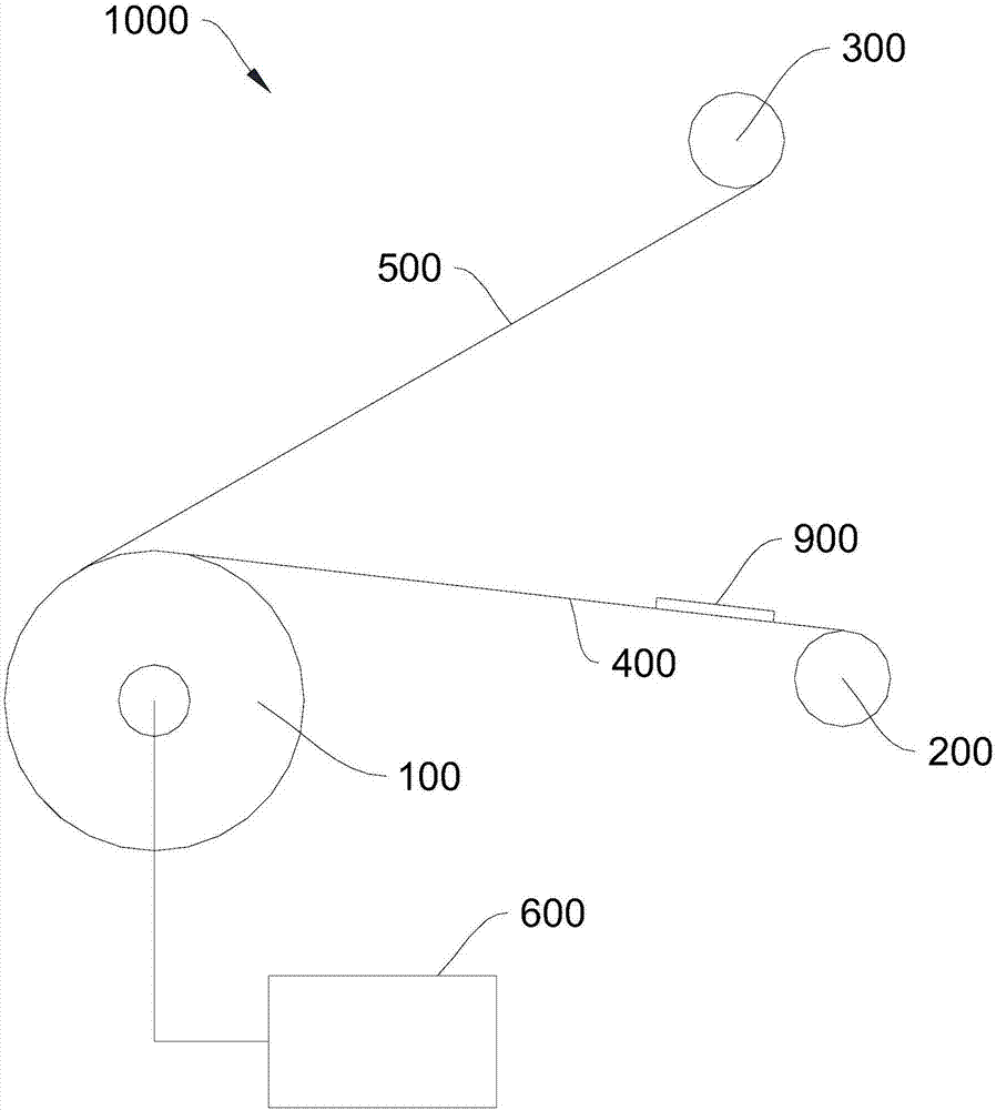
[0039] Please refer to figure 1 ,, this embodiment provides a medium conveying device 1000 , which includes a reel 100 , a first drum 200 , a second drum 300 , a first conveyor belt 400 , a second conveyor belt 500 and a driving motor 600 . Both ends of the first conveyor belt 400 are respectively wound on the reel 100 and the first drum 200 , and both ends of the second conveyor belt 500 are respectively wound on the reel 100 and the second drum 200 . The rotating drum 300, the reel 100 is electrically connected with the driving motor 600, and the driving motor 600 is used to drive the reel 100 to rotate clockwise or counterclockwise and drive the first conveyor belt 400 and the The second conveyor belt 500 moves along with the reel 100 . Wherein, the width of the first conveyor belt 400 is greater than the width of the preset medium 900 .

[0040] In this embodiment, the preset medium 900 may be banknotes, coins and other cash. It can be understood that the preset medium ...

no. 2 example

[0056] Please refer to Figure 4 , this embodiment provides a medium conveying device 1000, the biggest difference from the first embodiment above is that, in this embodiment, between the first conveying belt 400 and the second conveying belt 500 close to the first A conveying belt 400 is provided with a medium stretching part, and there is a gap between the medium stretching part and the first conveying belt 400 , and the rotation direction of the medium stretching part is opposite to that of the reel 100 .

[0057] In this embodiment, the medium stretching part includes a first conveying roller 710 and a second conveying roller 720 arranged in sequence along the direction close to the rotating shaft, and the first conveying roller 710 and the second conveying roller 720 are driven The first conveying roller 710 and the second conveying roller 720 rotate in the same direction, and the position of the first conveying roller 710 is higher than that of the second conveying rolle...

no. 3 example

[0061] Please refer to Figure 6 , this embodiment provides a medium conveying device 1000, the biggest difference from the first embodiment above is that in this embodiment, the second conveying belt 500 wound on the reel 100 is far away from the reel 100 One side of the second conveyor belt 500 is also provided with a rear end holding part 800, and the rear end holding part 800 is against the side of the second conveyor belt 500 away from the reel 100, and the movement of the second conveyor belt 500 can drive the The rear end holding part 800 is rotated.

[0062] In this embodiment, preferably, the rear end holding part 800 is connected to the driving motor 600, and the driving motor 600 is used to drive the rear end holding part 800 to rotate in the direction opposite to the rotation direction of the reel 100. . The rear end holding part 800 is driven to rotate by an external force through the driving motor 600, so that the preset medium 900 is under stronger pressure fr...


PUM


Abstract

The invention provides a medium conveying device and a medium conveying system, and relates to the automatic cash recycling system field. The medium conveying device comprises a scroll, a first drum, a second drum, a first conveyor belt, a second conveyor belt, and a driving motor. The two ends of the first conveyor belt are disposed on the scroll and the first drum respectively in a coiled manner, and the two ends of the second conveyor belt are disposed on the scroll and the second drum respectively in a coiled manner. The scroll is electromechanically connected with the driving motor, and the driving motor is used to drive the scroll to rotate along a clockwise direction or a counterclockwise direction, and is used to drive the first conveyor belt and the second conveyor belt to move along with the scroll. The width of the first conveyor belt is greater than a width of a preset medium. Compared with the prior art, the medium conveying device and the medium conveying system are advantageous in that the first conveyor belt having the width greater than the preset medium width is used to convey the preset medium, and the preset medium having cracks are prevented from exceeding the two sides of the first conveyor belt, and the curling or the tearing of the medium is prevented.

Description

technical field [0001] The invention relates to the field of automatic deposit and withdrawal machines, in particular to a medium conveying device and system. Background technique [0002] At present, the cash ATMs widely used in financial institutions such as banks and stock exchanges can make customers deposit cash such as banknotes and coins or pay customers in cash according to the transaction content with customers. [0003] Existing cash automatic teller machine, it can be provided with identification device by the banknote inlet and outlet that carries out banknote giving and receiving between customers, and through this authentication device, the banknote that puts into banknote outlet is authenticated. For the banknotes identified as genuine banknotes, they can be transported to the currency box for storing banknotes through the conveying device; while for the banknotes identified as counterfeit or abnormal banknotes, they will be returned to the banknote exit throu...

Claims


Application Information

Patent Timeline
IPC IPC(8): G07D11/00
CPCG07D11/10
Inventor 陈星
Owner SHENZHEN YIHUA COMP
Why Eureka
Try Eureka