
Method for measuring the internal reflection coefficient of photovoltaic ribbon and measuring i of different ribbon components sc method of difference

A technology of photovoltaic welding ribbon and measurement method, which is applied in the field of solar cells, can solve the problem of inability to measure the internal reflection coefficient of the welding ribbon, and achieve the effect of avoiding power loss and simplifying the evaluation process.

Active Publication Date: 2019-09-20
ATESI PHOTOVOLTAI SCI & TECH SUZHOU +1
View PDF5 Cites 0 Cited by
  • Summary
  • Abstract
  • Description
  • Claims
  • Application Information

AI Technical Summary

Problems solved by technology

[0004] The first purpose of the present invention is to provide a method for measuring the internal reflection coefficient of the photovoltaic ribbon, so as to alleviate the technical problem that the internal reflection coefficient of the solar ribbon cannot be measured in the prior art

Method used


Image

  • Method for measuring the internal reflection coefficient of photovoltaic ribbon and measuring i of different ribbon components  <sub>sc</sub> method of difference
  • Method for measuring the internal reflection coefficient of photovoltaic ribbon and measuring i of different ribbon components  <sub>sc</sub> method of difference
  • Method for measuring the internal reflection coefficient of photovoltaic ribbon and measuring i of different ribbon components  <sub>sc</sub> method of difference

Examples


Embodiment 1

[0068] This embodiment is a method for measuring the internal reflection coefficient of a photovoltaic ribbon, comprising the following steps:

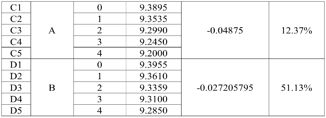
[0069] Step a): Select 10 pieces of 5-busbar monocrystalline cells with a side length of 156.75mm and an area of ​​244cm 2 , the Isc distribution of these 10 cells is in the range of 9.5A-9.51A, the reflectivity is in the range of 5%-5.5%, and the SiN refractive index is distributed in the range of 2.04-2.07;

[0070] Divide the above 10 cells into 2 groups, 5 cells in each group, numbered C1-C5 and D1-D5 in sequence, where C1-C5 is one group and D1-D5 is another group;

[0071] Step b): Solder the front and back sides of the above 10 cells with welding strips and bus bars respectively;

[0072] Step c): Place the solder ribbon A to be tested (0.9mm in width and 160mm in length) on the surface of the cells C1-C5, and place the solder ribbon B to be tested (0.9mm in width and 160mm in length) on the cell surfaces of C6-C10;

[0073] ...

Embodiment 2

[0097] This embodiment is a method for measuring the internal reflection coefficient of a photovoltaic ribbon, comprising the following steps:

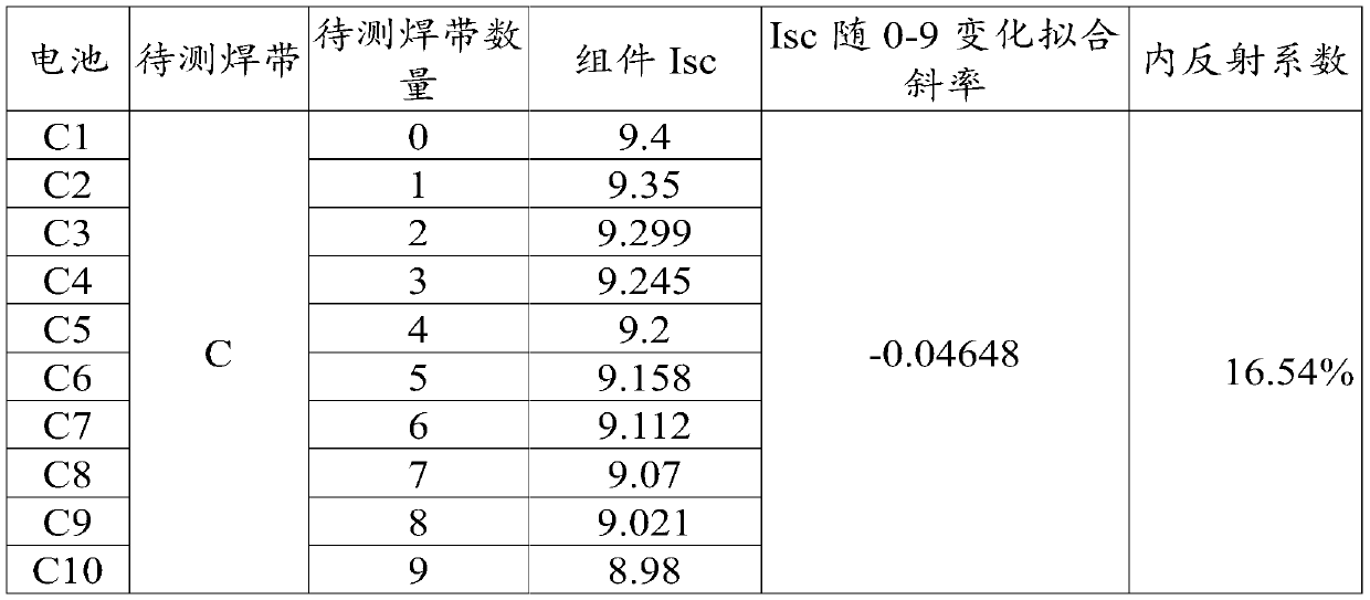
[0098] Step a): Select 10 pieces of 5-busbar monocrystalline cells with a side length of 156.75mm and an area of ​​244cm 2 , the Isc distribution of these 10 solar cells is in the range of 9.5A-9.51A, the reflectivity is in the range of 5%-5.5%, and the SiN refractive index is distributed in the range of 2.04-2.07; the above 10 solar cells are numbered sequentially as C1-C10;

[0099] Step b): Solder the front and back sides of the above 10 cells with welding strips and bus bars respectively;

[0100] Step c): Place the solder strip C (width 0.9mm, length 160mm) on the surface of the cell C1-C10;

[0101] C1 cell does not put extra solder ribbon C to be tested, C2 cell puts 1 solder ribbon C to be tested, C3 cell puts 2 solder ribbons C to be tested, C4 cell puts 3 solder ribbons C to be tested,... , and so on, put 9 solder ribbons...

Embodiment 3

[0110] This embodiment is a method for measuring the internal reflection coefficient of a photovoltaic ribbon, comprising the following steps:

[0111] Step a): Select 2 pieces of 5-busbar monocrystalline cells with a side length of 156.75mm and an area of ​​244cm 2 , the Isc distribution of these two cells is in the range of 9.5A-9.51A, the reflectivity is in the range of 5%-5.5%, and the SiN refractive index is distributed in the range of 2.04-2.07; the above 10 cells are numbered in turn as C1-C2;

[0112] Step b): Solder the front and back sides of the above two cells with welding strips and bus bars respectively;

[0113] Step c): Place the solder strip D (width 0.9mm, length 160mm) on the surface of the battery sheet of C1-C2;

[0114] The C1 cell does not put an extra solder ribbon D to be tested, and the C2 cell puts one solder ribbon D to be tested;

[0115] Step d): The method of placing the soldering ribbon C to be tested in the step c) is: place the soldering ri...


PUM


Abstract

The invention provides a test method for an internal reflection coefficient of a photovoltaic welding strip and a method for testing I<SC> difference among different welding strip assemblies, and relates to the field of a solar cell. The test method for the internal reflection coefficient of the photovoltaic welding strip comprises the following steps of selecting n battery pieces, placing welding strips to be tested on front surfaces of the battery piece, and placing (m-1) welding strips to be tested on a front surface of an m(th) battery piece; packaging the battery pieces on which the welding strips to be tested are placed respectively by package materials to form assemblies, and testing I<SC> of each assembly, wherein I<SC1> is a short-circuit current of the assembly on which the welding strips to be tested are not placed; and making a discrete diagram by taking numbers of the welding strips to be tested placed on the battery pieces as a horizontal coordinate and the I<SC> as a longitudinal coordinate, and obtaining a straight line after fitting, wherein the fitting slope of the straight line is k, and the internal reflection coefficient T of the welding strip to be tested is equal to {1+[k*(area of the battery piece after a main grid is removed)] / [(I<SC1>*(width of the welding strip to be tested)*(length of the battery piece)]}.

Description

technical field [0001] The invention relates to the technical field of solar cells, in particular to a method for measuring the internal reflection coefficient of a photovoltaic ribbon and measuring the I of different ribbon components. SC method of difference. Background technique [0002] For solar cell modules, there are three parts where the light goes after it hits the ribbon. The first part is the part absorbed by the ribbon, the second part is the part reflected into the air by the solder ribbon, and the third part is reflected by the ribbon directly to the cell or reflected to the interface between glass and air and then reflected back again. part of the battery. The proportion of the third part is the internal reflection coefficient of the welding strip. Different ribbons have different internal reflection coefficients. The internal reflection coefficient of the ribbon directly affects the power of the module. However, the internal reflection coefficient of the...

Claims


Application Information

Patent Timeline
Patent Type & Authority Patents(China)
IPC IPC(8): H01L21/66H01L31/05H01L31/18
CPCH01L22/12H01L22/14H01L31/0504H01L31/188Y02E10/50Y02P70/50
Inventor 万松博王栩生涂修文邢国强
Owner ATESI PHOTOVOLTAI SCI & TECH SUZHOU
Learn More