
A photoelectric monitoring system and monitoring method

A monitoring system and optoelectronic technology, applied in CCTV systems, components of TV systems, TVs, etc., can solve problems such as insufficient monitoring efficiency of optoelectronic monitoring systems, and achieve the effect of solving insufficient monitoring efficiency, facilitating integration, and improving efficiency

Active Publication Date: 2020-06-23
北京富吉瑞光电科技股份有限公司
View PDF4 Cites 0 Cited by
  • Summary
  • Abstract
  • Description
  • Claims
  • Application Information

AI Technical Summary

Problems solved by technology

[0004] In order to solve the above-mentioned problems in the prior art, the present invention provides a photoelectric monitoring system and a monitoring method to solve the technical problem of insufficient monitoring efficiency of the photoelectric monitoring system in the prior art

Method used


Image

  • A photoelectric monitoring system and monitoring method
  • A photoelectric monitoring system and monitoring method
  • A photoelectric monitoring system and monitoring method

Examples


Embodiment 1

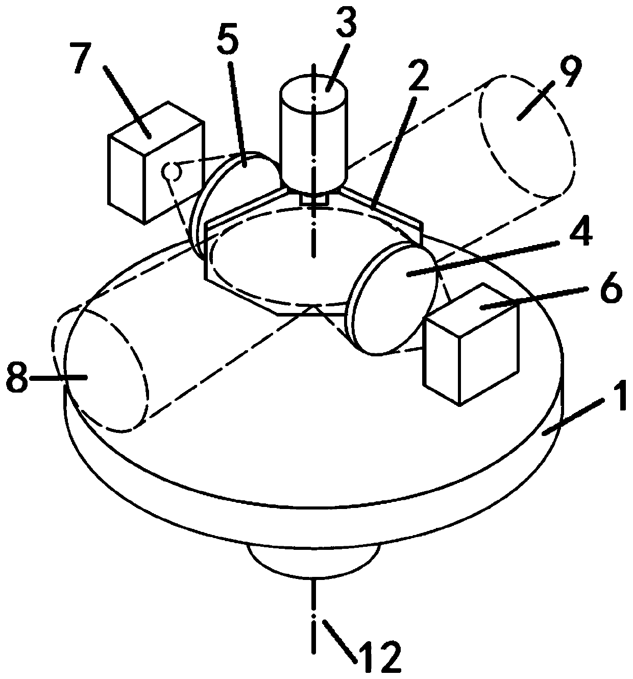
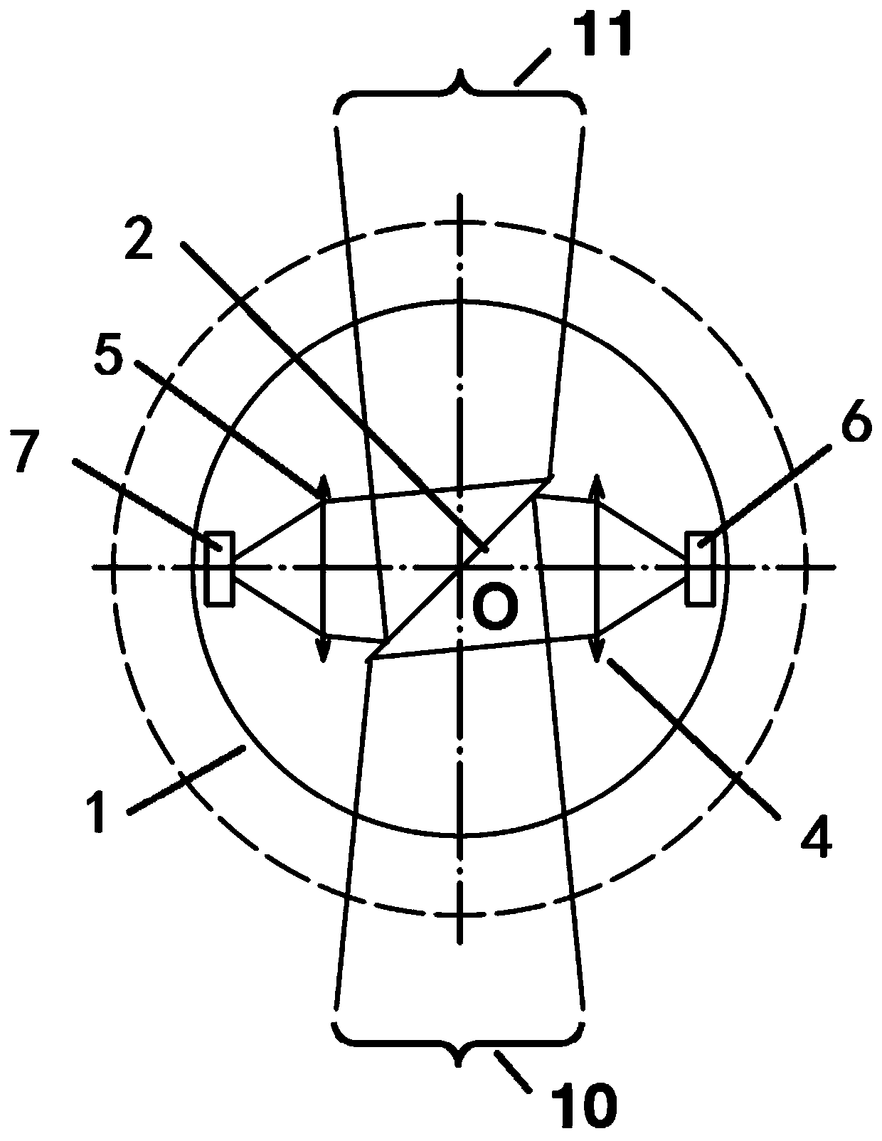
[0027] Such as figure 1 As shown, the present embodiment provides a photoelectric monitoring system, including a turntable 1, a turntable motor, a scanning mirror 2, a scanning mirror motor 3, lenses 4 and 5, sensors 6 and 7; the scanning mirror 2 is located on the turntable 1; Lenses 4 and 5, sensors 6 and 7 are respectively located on the left and right sides of the scanning mirror 2, and are symmetrically distributed, fixed on the turntable 1; the turntable motor is arranged on the horizontal rotating shaft of the turntable 1, and drives the turntable 1 around its horizontal rotating shaft 12 Rotate in the horizontal direction; the scanning mirror motor 3 is arranged on the horizontal rotating shaft of the scanning mirror 2, and drives the scanning mirror 2 to cooperate with the turntable 1 to perform periodical swing scanning around the horizontal rotating shaft of the scanning mirror 2.

[0028] Of course, the turntable 1 can also rotate in the pitch (vertical) direction ...

Embodiment 2

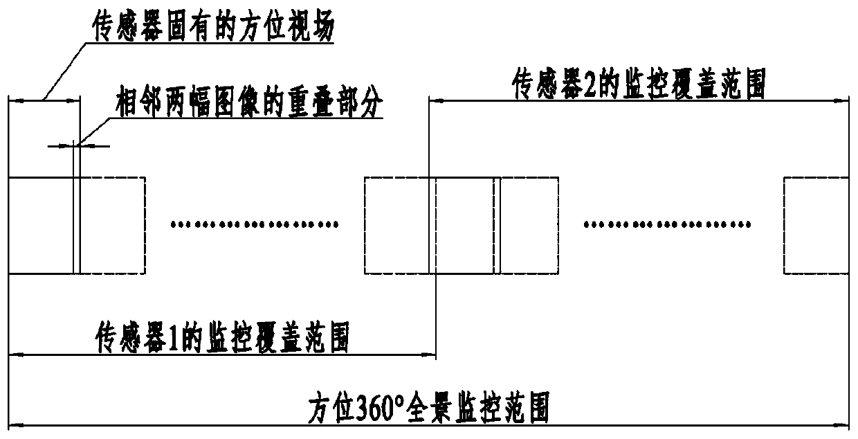
[0036] This embodiment provides a photoelectric monitoring method, which can be realized by using any photoelectric monitoring system provided in the above-mentioned embodiment 1. In order to better understand the present invention, the present invention will be specifically described below in conjunction with embodiment 1. Such as figure 2As shown, the photoelectric monitoring method specifically includes: by scanning the front and back sides of the mirror, the light rays in the front and back directions respectively relative to the 180-degree direction are collected simultaneously to form a 360-degree forward and reverse direction double optical path; The corresponding lenses on the dual optical paths are imaged on the corresponding sensors to obtain 360-degree peripheral images in different spectral bands. In combination with Embodiment 1, that is, the lens 4 is used in conjunction with the sensor 6, the lens 5 is used in conjunction with the sensor 7, and the lens 4, the ...


PUM


Abstract

The invention belongs to the technical field of monitoring and relates to a photoelectric monitoring system and a monitoring method. The system includes a turntable, a turntable motor, a scanning mirror, a scanning mirror motor, a lens and a sensor; the scanning mirror is located on the turntable; there are two lenses and two sensors respectively located on the left and right sides of the scanning mirror Both sides, and symmetrically distributed, are fixed on the turntable; the turntable motor is arranged on the horizontal rotating shaft of the turntable to drive the turntable to rotate around its horizontal rotating shaft; the scanning mirror motor is arranged on the scanning reflector On the horizontal rotation axis of the mirror, the scanning mirror is driven around its horizontal rotation axis to cooperate with the turntable to perform periodic swing scanning. Therefore, the technical problem of insufficient monitoring efficiency of the photoelectric monitoring system in the prior art is solved, and the technical effect of efficient monitoring is achieved.

Description

technical field [0001] The invention belongs to the technical field of monitoring, in particular to a photoelectric monitoring system and a monitoring method. Background technique [0002] With the deterioration of the global security situation, the possibility of terrorist attacks on important places is increasing. In the protection of important places, the photoelectric monitoring system has been widely used and played a great role. [0003] In order to improve the effectiveness of photoelectric monitoring, it is the goal pursued by photoelectric monitoring designers to obtain a wider monitoring area and more monitoring information in a short time. There are generally two ways to obtain a large-scale monitoring area. One is to use a large-field optical system to cover the monitoring area. Due to the large field of view, the focal length of the system is very short, and the resolution of the monitoring target is poor. The working distance is short, which limits the scope ...

Claims


Application Information

Patent Timeline
Patent Type & Authority Patents(China)
IPC IPC(8): H04N7/18H04N5/225H04N5/232
CPCH04N7/18H04N23/45H04N23/55H04N23/698
Inventor 李荣刚詹道教王瑛琳陈德光季云松
Owner 北京富吉瑞光电科技股份有限公司
Learn More