

Ileum colostomy catheter
A catheter and ostomy technology, applied in the field of medical devices, can solve the problems of inconvenience for patients and medical staff, narrowing of the lumen of the catheter, and difficulty in passing fecal residues, so as to reduce the probability of intestinal necrosis, facilitate the dredging of obstruction, and achieve The effect of clearing the obstruction
- Summary
- Abstract
- Description
- Claims
- Application Information
AI Technical Summary
Problems solved by technology
Method used
Image

Examples
Embodiment 1
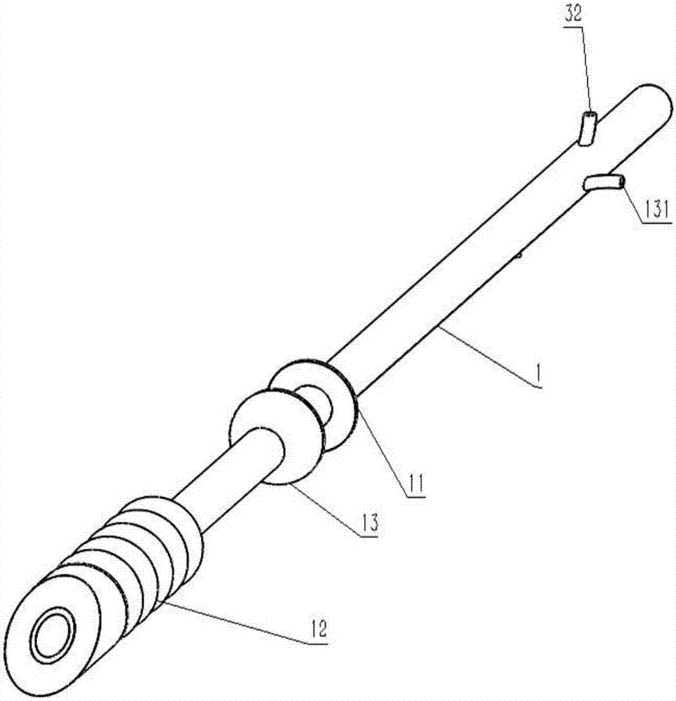
[0038] Embodiment 1: as Figure 1 to Figure 5 As shown, an adjustable ileostomy catheter includes a catheter body 1, the catheter body 1 is a flexible tube with openings at the upper and lower ends, with a hardness of about 85A, which can resist bending and will not easily collapse . The opening at the lower end of the tube body is in the shape of an oblique incision, so that it can be easily inserted into the intestinal tract during operation.
[0039] The upper portion of the outer wall of the catheter body 1 is provided with external threads, and is connected with a pressing piece 11 through threads.
[0040] The outer wall of the catheter tube 1 is also covered with a first balloon 12 and a second balloon 13, the first balloon 12 and the second balloon 13 are non-compliant balloons, which are not easy to leak after filling .
[0041] The first balloon 12 is sleeved on the outer wall of the lower end of the catheter tube body 1, the lower end of the first balloon 12 is c...
Embodiment 2
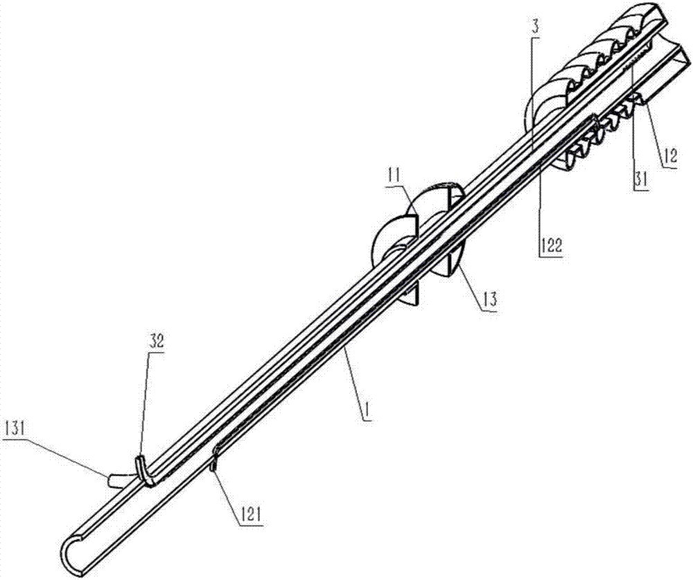
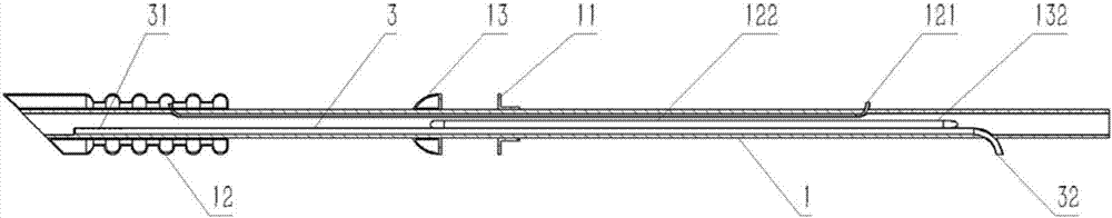
[0045] Embodiment 2: as figure 2 , image 3 , Figure 4 , Figure 5 As shown, on the basis of Example 1, in order to solve the problem of dredging the obstruction of the tube body, a flushing tube 3 can be set in the tube of the catheter tube 1, the lower end of the flushing tube 3 is closed, and a section of the side wall at the lower end There are a plurality of water outlet holes 31 leading into the conduit body 1 . A third injection port 32 is provided on the upper section of the catheter tube body 1, and the third injection port 32 is connected with the flushing pipe 3 to inject or draw water therefrom.
[0046] Such as Figure 2 to Figure 5 As shown, the shape of the flushing pipe 3 is linear, in fact, the flushing pipe 3 can also be set to other shapes, such as Figure 6 As shown, the flushing pipe 3 is spiral, and this arrangement is better than a straight line, because of the spiral design, the water outlet holes in the lower section can be arranged in a circula...
Embodiment 3
[0050] Embodiment 3: In Embodiment 2, a flushing tube 3 is arranged inside the catheter body 1 , and then water is injected into the flushing tube 3 from the third injection port 32 to dredge the obstruction.
[0051] This embodiment provides another structure to realize the function of unblocking the obstruction, and the technical solution is as follows:
[0052] Such as Figure 8 to Figure 13 As shown, on the basis of Embodiment 1, the upper opening of the catheter body 1 is closed with a silicone plug or connected with a control valve 7 .
[0053] A dredge can also be detachably connected to the upper opening of the catheter body 1 , and the dredge includes a handle 51 , a connecting portion 52 , a helical blade 53 and a connecting pipe 54 connected to the catheter body 1 . The connecting portion 52 and the connecting pipe 54 are engaged with each other.
[0054] The inner wall of the connecting pipe 54 is provided with a snap-in protrusion 541, and the connecting portion...
PUM
 Abstract
Description
Claims
Application Information