Automatic pipe bender for stainless steel pipes and bending method thereof

A stainless steel pipe and pipe bending machine technology, applied in the direction of feeding device, positioning device, storage device, etc., can solve the problem of piston cylinder stroke, driving force cannot be adjusted accurately, reduce the bending efficiency of the pipe bender, and cannot be precisely bent, etc. problems, to achieve the effect of improving bending accuracy and bending stability, reducing labor intensity and labor costs, and improving bending efficiency

Inactive Publication Date: 2017-09-26
HUNAN KUANGCHU TECH CO LTD
View PDF8 Cites 11 Cited by
  • Summary
  • Abstract
  • Description
  • Claims
  • Application Information

AI Technical Summary

Problems solved by technology

For example, the application number is "201620754733.9" and the name is "a high-efficiency steel pipe bending machine". It uses a vertical piston cylinder to directly drive the bending pipe seat to bend the pipe. The biggest disadvantage is that the stroke of the piston cylinder 1. The driving force cannot be adjusted accurately, and the steel pipe can only be roughly bent, not finely bent; moreover, the steel pipe after bending can only be taken out manually because the shape changes from straight to U-like curved; manual operation , the first is low efficiency, which reduces the bending efficiency of the entire pipe bender, and the second is the existence of safety risks

Method used


Image

  • Automatic pipe bender for stainless steel pipes and bending method thereof
  • Automatic pipe bender for stainless steel pipes and bending method thereof
  • Automatic pipe bender for stainless steel pipes and bending method thereof

Examples


Embodiment Construction

[0045] The specific implementation of the present invention will be further described below in conjunction with the accompanying drawings, so as to fully understand and implement the process of how to apply technical means to solve technical problems and achieve technical effects in the present invention. It should be noted that, as long as there is no conflict, each embodiment and each feature in each embodiment of the present invention can be combined with each other, and the formed technical solutions are all within the protection scope of the present invention.

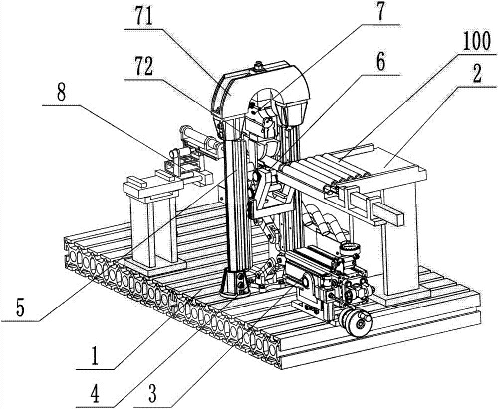
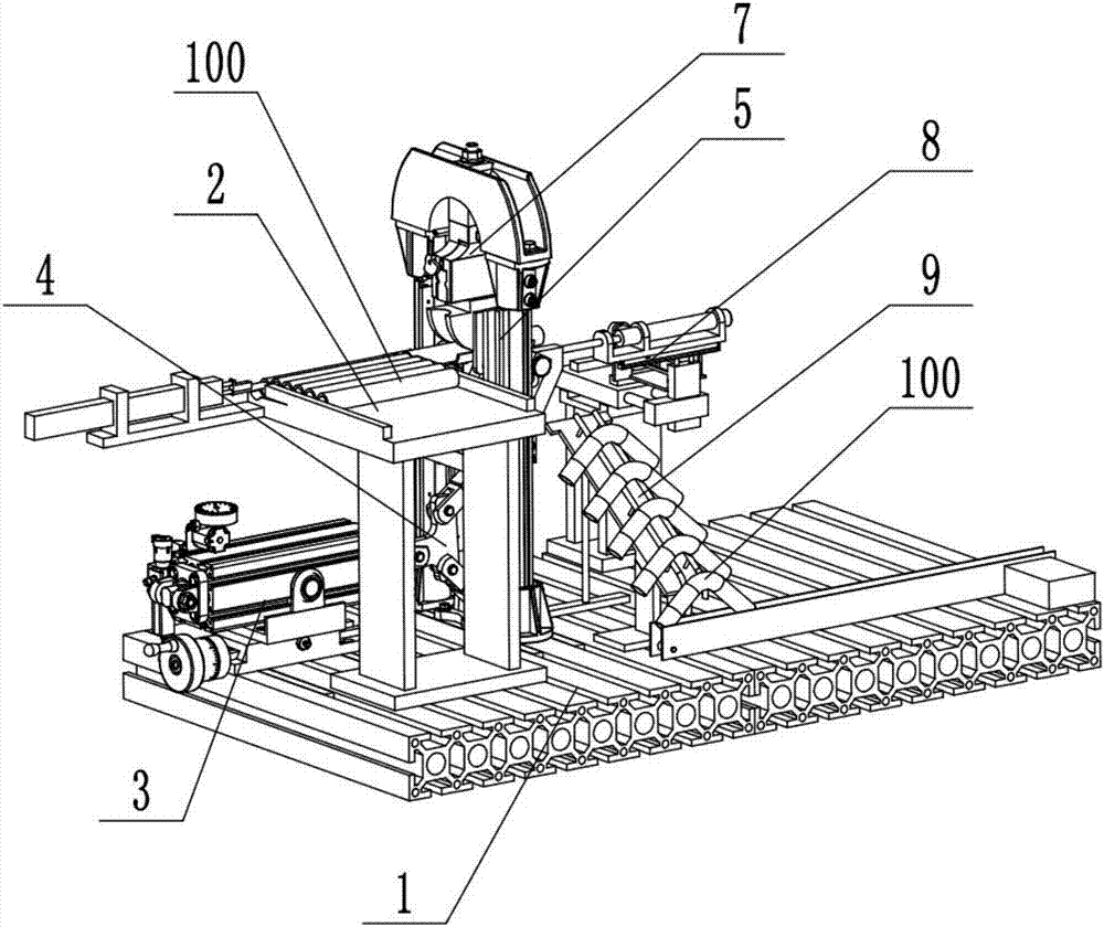
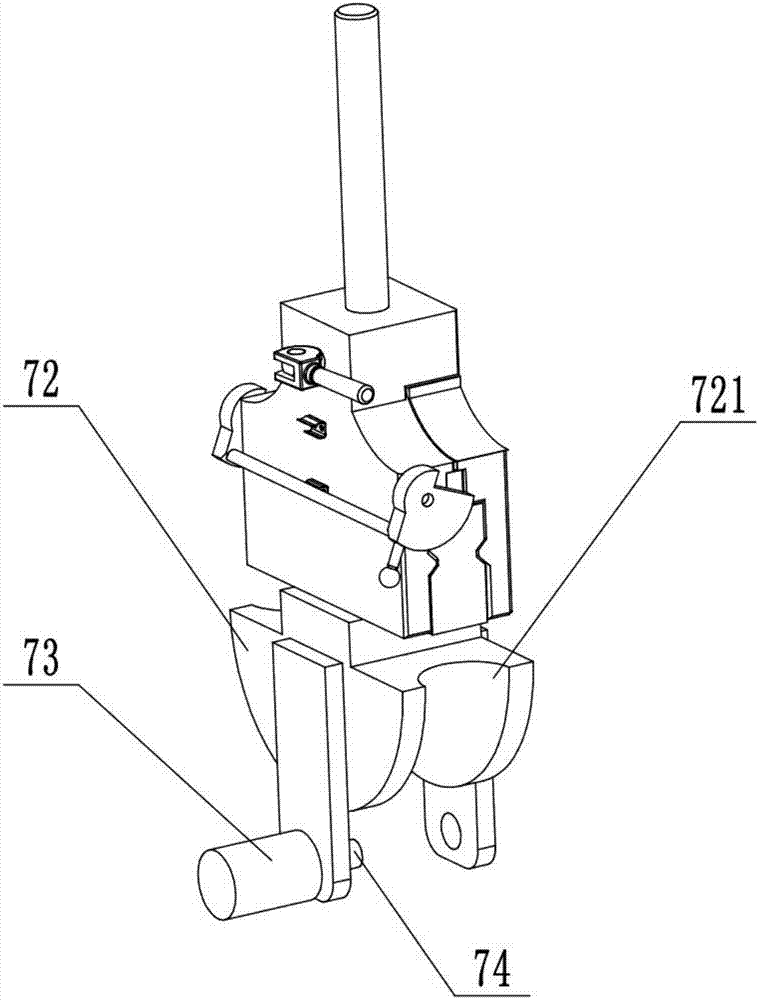
[0046] Such as Figure 1 to Figure 4 As shown, the stainless steel pipe automatic pipe bending machine of this embodiment includes a base 1, a bending frame 5 installed on the base, a bending head assembly 7 fixed on the upper end of the bending frame 5, and can be vertically mounted on the bending frame 5. To the sliding bending seat 6 and the bending driving device for driving the bending seat 6, the bending hea...


PUM


Abstract

The invention relates to an automatic pipe bender for stainless steel pipes and a bending method thereof. The automatic pipe bender comprises a base, a bending frame, a bending head assembly, a bending seat and a bending driving device, wherein the bending frame is installed on the base, the bending head assembly is fixed to the upper end of the bending frame, the bending seat can vertically slide on the bending frame, the bending driving device is used for driving the bending seat, the bending head assembly comprises a bending head fixed seat which is fixed to the upper end of the bending frame and a bending head which is fixed to the lower part of the bending head fixed seat, and a steel pipe bending groove is formed in the lower end of the bending head; the bending seat comprises a V-shaped bending fixed seat which is installed on the bending frame in a sliding mode through vertical guide wheels on both sides, and a plurality of bending abutting rods are arranged on the V-shaped bending fixed seat; and a steel pipe feeding device, an elbow taking device and an elbow output device are further installed on the base. The automatic pipe bender has the advantages of high bending accuracy, high bending stability, high bending efficiency and low labor intensity.

Description

technical field [0001] The invention relates to the field of automatic mechanical equipment, in particular to automatic bending equipment for steel pipes. Background technique [0002] Steel pipe bending equipment is used to bend steel pipes. For example, the application number is "201620754733.9" and the name is "a high-efficiency steel pipe bending machine". It uses a vertical piston cylinder to directly drive the bending pipe seat to bend the pipe. The biggest disadvantage is that the stroke of the piston cylinder 1. The driving force cannot be adjusted accurately, and the steel pipe can only be roughly bent, not finely bent; moreover, the steel pipe after bending can only be taken out manually because the shape changes from straight to U-like curved; manual operation , the first is low efficiency, which reduces the bending efficiency of the entire pipe bender, and the second is a safety risk. Contents of the invention [0003] In view of the problems still existing i...

Claims


Application Information

Patent Timeline
Patent Type & Authority Applications(China)
IPC IPC(8): B21D7/16B21D43/13B21D45/02B21D43/00
CPCB21D43/006B21D7/16B21D43/003B21D43/13B21D45/02
Inventor 肖坤坚
Owner HUNAN KUANGCHU TECH CO LTD
Why Eureka
Try Eureka