
Air compressor noise reduction pipe

An air compressor and noise reduction technology, which is applied in the field of connecting pipes, can solve the problems of not being able to meet the market demand, the working environment is not optimistic, and increase the noise reverberation, and achieve the effect of easy promotion, convenient installation, and reduced vibration amplitude

Inactive Publication Date: 2017-09-26
HARBIN HONGWANZHI SCI & TECH DEV
View PDF4 Cites 0 Cited by
  • Summary
  • Abstract
  • Description
  • Claims
  • Application Information

AI Technical Summary

Problems solved by technology

[0004] Currently, The use and design of the pipelines of the air compressor are mostly connected by common metal pipelines to complete the air purification, compression, transmission and other processes, and some noise will be generated during the air compression process, and the noise is transmitted through the pipeline , increasing the effect of noise reverberation, resulting in a more unoptimistic working environment and failing to meet market demand

Method used


Image

  • Air compressor noise reduction pipe

Examples


Embodiment 1

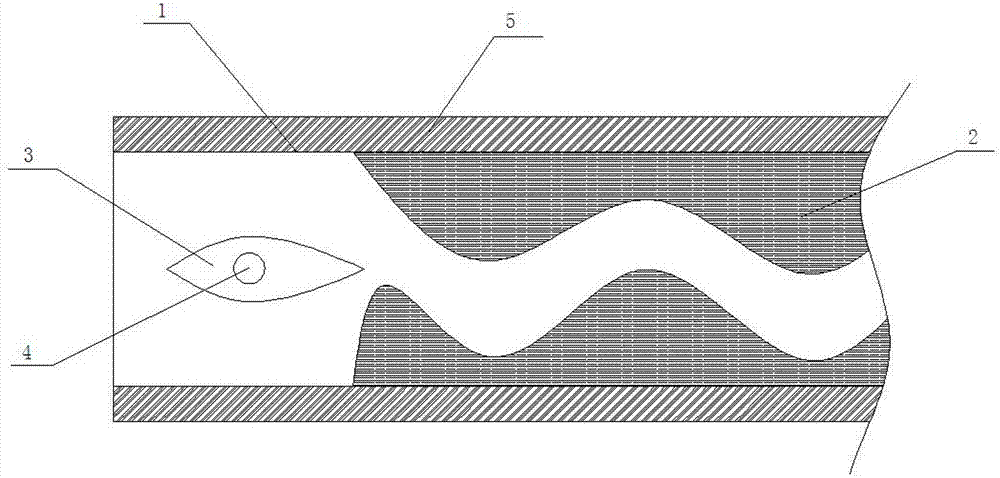
[0018] An air compressor noise reduction tube, including a tube body 1; it is characterized in that: one end of the tube body 1 is provided with a shuttle-shaped airflow buffer 3, and the two sides of the shuttle-shaped airflow buffer 3 are connected by connecting rods 4 On the inner wall of the pipe body 1; the inside of the pipe body 1 is provided with a shock-absorbing and impact-resistant material 2 behind the shuttle-shaped airflow buffer 3, and the shock-absorbing and impact-resistant material 2 forms a spiral channel inside the pipe body 1; the pipe A sound-insulating material layer 5 is provided on the outer wall of the body 1 .

[0019] The sound-insulating material layer 5 is made of sound-insulating cotton.

[0020] The shock-absorbing and impact-resistant material 2 is made of rubber.

Embodiment 2

[0022] Working principle of the present invention: the present invention divides the air entering the pipe through the shuttle-shaped airflow buffer 3, thereby reducing the pressure of the air in the pipe, and reduces the impact force of the air through the shock-absorbing and impact-resistant material 2 in the pipe, and at the same time Compressed air flows in the path inside the tube, and the spiral channel formed in the tube prolongs the flow path of the air, increases the flow distance, reduces the flow velocity of the air, and increases the thickness of the tube body 1, increasing the shock absorption method, thereby The noise generated by high-speed air flow is reduced; and the noise inside the pipe body 1 is further reduced by wrapping the pipe wall with the sound-insulating material layer 5 , achieving a good noise reduction purpose.

Embodiment 3

[0024] The present invention is suitable for high-speed airflow transmission device, which is convenient to reduce the noise generated by high-speed air flow, effectively reduces the vibration frequency in the high-speed air flow, and further absorbs the generated noise through the outer layer of sound-absorbing material or diffuse.


PUM


Abstract

The invention discloses an air compressor noise reduction pipe. The noise reduction pipe comprises a pipe body and is characterized in that a fusiform air flow buffer part is arranged at one end in the pipe body, two sides of the fusiform air flow buffer part are connected to the inner wall of the pipe body through connecting rods, damping impact resistance materials are arranged at the position, behind the fusiform air flow buffer part, in the pipe body, and the damping impact resistance materials form a spiral channel in the pipe body, a sound insulation material layer is arranged on the outer wall of the pipe body, and is made of sound insulation cotton, and the damping impact resistance materials are made of rubber. The air compressor noise reduction pipe has the beneficial effects that erosion prevention and noise reduction are achieved, impact resistance is achieved, manufacturing is facilitated, use is convenient, mounting is convenient, cost is low, and popularization is easy.

Description

technical field [0001] The invention relates to a connecting pipe, in particular to an air compressor noise reduction pipe. Background technique [0002] Air compressor is the basic product of industrial modernization. It is often said that electrical and automation have the meaning of full pneumatic; and air compressor is to provide air source power, which is the main body of the electromechanical air source device, which is the core equipment of the pneumatic system. It is a device that converts the mechanical energy of the prime mover (usually an electric motor) into gas pressure energy, and is a gas pressure generating device for compressed air. [0003] Air compressors are essential equipment for various factories, road construction, mines and construction industries. They are mainly used to provide a steady stream of compressed air with a certain pressure, such as supplying air to pneumatic valves and supplying air to processes that require a certain pressure of g...

Claims


Application Information

Patent Timeline
IPC IPC(8): F04B39/00F04C29/06
CPCF04B39/0083F04C29/063F04C29/068F04C2270/135
Inventor 王雷
Owner HARBIN HONGWANZHI SCI & TECH DEV
Learn More