
Testing device for relay protection outlet circuit

A technology of loop testing and relay protection, which is applied to measuring devices, components of electrical measuring instruments, measuring electrical equipment, etc., can solve problems such as data floating, and achieve the effect of easy operation and improved working accuracy

Inactive Publication Date: 2017-09-26
国网河南省电力公司超高压公司
View PDF2 Cites 1 Cited by
  • Summary
  • Abstract
  • Description
  • Claims
  • Application Information

AI Technical Summary

Problems solved by technology

Including the shell, the power switch set on the front panel of the shell, the bus branch display panel, the reset button, and the indicator light group, the bus branch display panel is provided with the bus wiring diagram, and the bus wiring diagram is embedded with a branch knife Brake position display lamp, branch knife switch position knob switch and bus tie circuit breaker position knob switch; a circuit board is arranged in the housing, and the circuit board is composed of a switch-in circuit and an exit circuit, and the drive-in circuit includes a switch position switch The branch circuit, bus coupler open-in branch circuit and failure open-in branch circuit; it is not equipped with anti-drop protection and internal environment temperature balance in the device, which is prone to drop or data fluctuation caused by environmental influences
[0007] Therefore, there is a need for a phenomenon that can be used in different natural environments, and even when a high-altitude fall occurs, the device can be safely protected to ensure that the internal structure will not be damaged, which will cause the device to fail the test.

Method used


Image

  • Testing device for relay protection outlet circuit
  • Testing device for relay protection outlet circuit
  • Testing device for relay protection outlet circuit

Examples


Embodiment 1

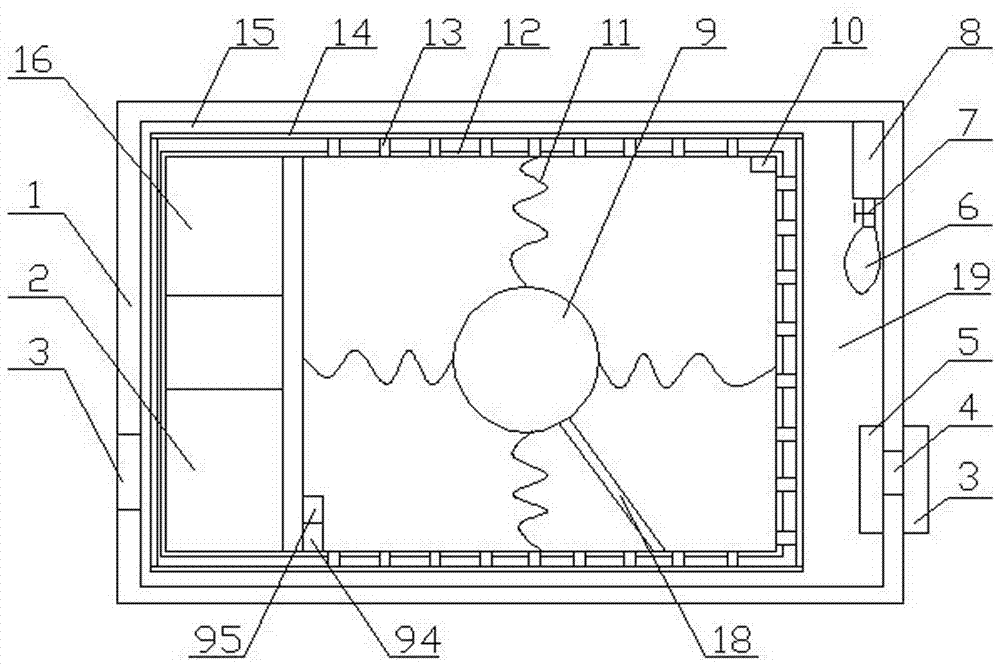
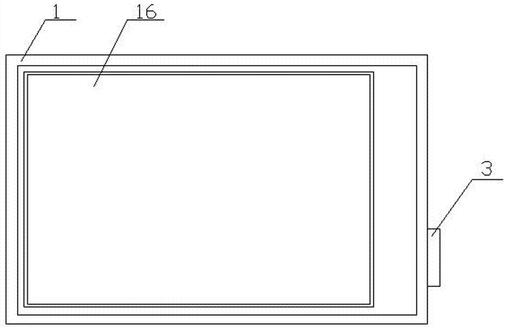
[0032] A relay protection outlet circuit test device, comprising a housing 1, a test module arranged in the housing 1, a plurality of test modules for connecting with the test module 9 are arranged on the surrounding wall of the housing 1 Measuring terminal 3;

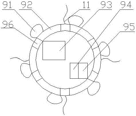
[0033] The test module 9 includes a touch display screen 16 arranged on the surface of the casing 1, a processor 93 arranged in the casing 1 for data processing, and a processor 93 arranged in the casing 1 for providing electric energy. A rechargeable battery 16, a charging controller 2 connected to the rechargeable battery 16, and a thermal balance adjustment module connected to the processor 93;

[0034] The processor 93 is arranged on a dynamic balance mechanism capable of protecting when falling, and the dynamic balance mechanism is connected with the inner wall 12 of the housing;

[0035] The dynamic balance mechanism includes a load-bearing chamber 92 for setting a processor 93, a plurality of elastic support mo...

Embodiment 2

[0039] The difference between it and Embodiment 1 is that the cooling pole 5 of the semiconductor cooling chip is connected to the heat conduction module, the heating pole 3 is arranged on the outer wall of the casing 1, and the cooling pole 5 and the heating pole 3 Bridge metal blocks 4 are set between them;

[0040] The heat conduction module includes a heat conduction chamber 19 arranged on one side of the housing 1 and communicating with the cavity 15 , and a plurality of heat conduction metal rods disposed in the heat conduction chamber 19 and the cavity 15 14. The inner wall of the housing 1 is provided with a metal block 13 for heat conduction, and the heat conduction chamber 19 is provided with the same heat conduction medium as that of the cavity 15 .

[0041] In this embodiment, the processor is arranged on the dynamic balance mechanism, and the dynamic balance mechanism can be connected with the inner wall of the housing; the dynamic balance mechanism adopted includ...

Embodiment 3

[0044] The difference between it and the second embodiment is that: both the bearing chamber 92 and the housing are provided with a MEMS accelerometer 94 and a MEMS gyroscope 95, and the bearing chamber 92 includes a spherical housing, which is arranged on the A plurality of cooling holes 96 on the spherical housing, a plurality of rubber airbags 91 provided on the spherical housing, and the elastic support module 11 provided on the spherical housing;

[0045] The elastic support module 11 includes six springs arranged on the inner wall of the housing, and the springs are connected to the bearing chamber 92 through the rubber bands.

[0046] The heat conduction module used in this embodiment includes a heat conduction chamber arranged on one side of the housing and communicated with the cavity, a plurality of heat conduction metal rods arranged in the heat conduction chamber, and the inner wall of the housing is set The metal block used for heat conduction, the same heat condu...


PUM


Abstract

The invention discloses a testing device for a relay protection outlet circuit. The testing device comprises a casing and a testing module arranged in the casing, wherein a plurality of measuring terminals for being connected with the testing module are arranged on the enclosing wall of the casing; the testing module comprises a touch display screen arranged on the surface of the casing, a processor which is arranged in the casing and used for carrying out data processing, a rechargeable battery which is arranged in the casing and used for providing electric energy, a charging controller communicated with the rechargeable battery as well as a thermal balance adjusting module connected with the processor. The thermal balance adjusting module and a dynamic balancing mechanism are arranged in the device and can be used for protecting the device, so that the device can be kept in a stable environment, and the phenomenon of internal damage due to missing fall can be avoided.

Description

technical field [0001] The invention relates to the technical field of relay protection devices, in particular to a relay protection outlet circuit testing device. Background technique [0002] With the rapid development of the power system, the scale of the power grid is growing day by day, and the network structure of the power system is more complex. It is particularly important to improve the safe operation level of the power system. Due to the particularity of the power system, the occurrence of electrical faults is inevitable. During the operation of the power system, if a local power grid or electrical equipment accident occurs and cannot be effectively controlled, it will inevitably cause damage to the stability of the power grid and a large-scale blackout accident; modern large power grids are more dependent on relay protection. The requirements for the correct rate of its movements are higher. [0003] The relay protection device is an important part of the power...

Claims


Application Information

Patent Timeline
Patent Type & Authority Applications(China)
IPC IPC(8): G01R31/00G01R1/02
CPCG01R31/00G01R1/02
Inventor 蒋亚东侯可曹甦惠张文博柳鑫刘霄扬王泾良安百峰刘畅白月杨艺瑾曹东升王莉曲欣王毅李璐王兴友付强王雷段五王彦坤拓四梅郭培陈宇王琪段鑫王佩朱红艳李景红
Owner 国网河南省电力公司超高压公司
Learn More