
Display imaging system, method thereof and vehicle with display imaging system

A display imaging and imaging technology, applied in optics, instruments, optical components, etc., can solve problems such as attenuation, complex manufacturing process, and low penetration rate of specific wavelength light

Active Publication Date: 2017-09-26
FUTURUS TECH CO LTD
View PDF21 Cites 11 Cited by
  • Summary
  • Abstract
  • Description
  • Claims
  • Application Information

AI Technical Summary

Problems solved by technology

[0004] However, these imaging methods using p-polarized light generally have the following defects: if a relatively high reflectivity is required, the transmittance will decrease, thus reducing the observation effect on the external environment, resulting in a relatively high brightness requirement for the image source
[0007] 1. It is easy to produce double images;
[0008] 2. If a relatively high reflectivity is required, the transmittance will be reduced, thus reducing the observation effect on the external environment
The disadvantage of this technology is that the penetration rate of light of specific wavelengths is not high. For example, the low penetration rate of red light, green light, blue light and other wavelengths will greatly weaken the traffic lights (red light, green light, yellow light). There is a very big safety hazard; moreover, the imaging angle of this technology is limited, and the imaging effect is not good; moreover, this technology needs to be plated with about 70 layers of thin film, and the manufacturing process is too complicated

Method used

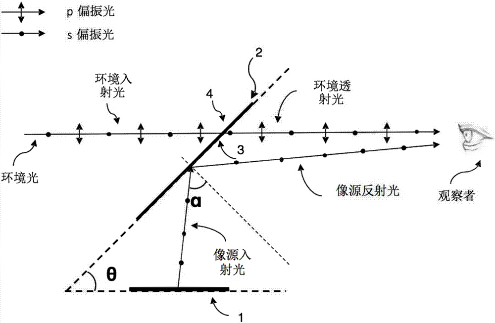
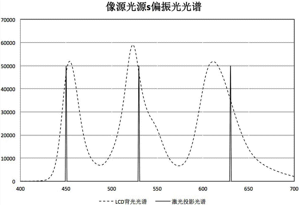
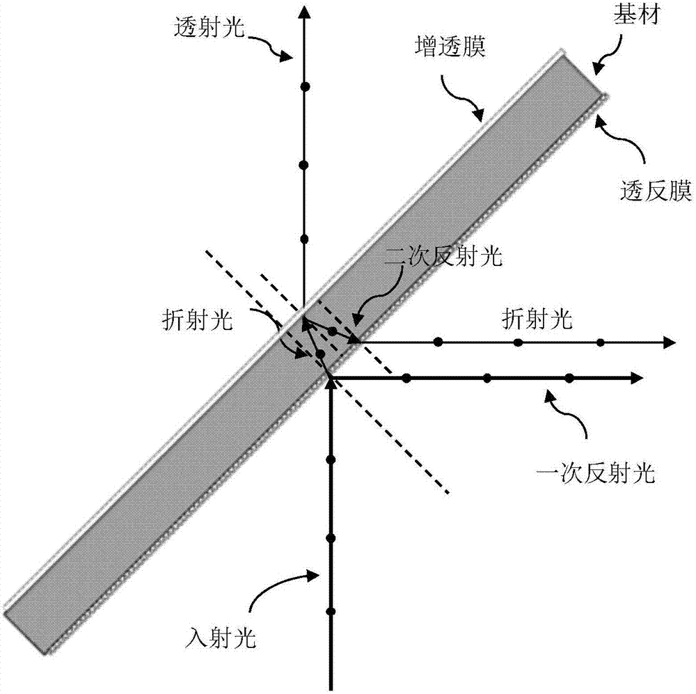

Image

  • Display imaging system, method thereof and vehicle with display imaging system
  • Display imaging system, method thereof and vehicle with display imaging system
  • Display imaging system, method thereof and vehicle with display imaging system

Examples


Embodiment Construction

[0085] In order to make the object, technical solution and advantages of the present invention clearer, the present invention will be further described in detail below in conjunction with the accompanying drawings.

[0086] For the sake of brevity and intuition in description, the solution of the present invention is described below by describing several representative implementation manners. Numerous details in the embodiments are only used to help the understanding of the solutions of the present invention. But obviously, the technical solutions of the present invention may not be limited to these details when implemented. In order to avoid unnecessarily obscuring the solution of the present invention, some embodiments are not described in detail, but only a framework is given. Hereinafter, "including" means "including but not limited to", and "according to..." means "at least according to, but not limited to only based on...". "First", "second" and so on are only used to ...


PUM

PropertyMeasurementUnit
full width at half maximumaaaaaaaaaa
reflectanceaaaaaaaaaa
transmittivityaaaaaaaaaa

Abstract

The invention provides a display imaging system, a display imaging method and a head-up display device. The display imaging system comprises the components of an imaging window which comprises a transflective film; and an image source which is used for transmitting s polarized light that is incident to the transflective film; wherein the average reflectivity of the transflective film to the s polarized light is higher than 50%, and the imaging window is used for transmitting ambient light. The display imaging system, the display imaging method and the head-up display device have advantages of reducing a requirement for brightness of the image source, eliminating ghosts, realizing a better visual effect and reducing cost.

Description

technical field [0001] The embodiments of the present invention relate to the field of optoelectronic technology, and more specifically, to a display imaging system and a corresponding imaging method; and to a vehicle including the display imaging system. Background technique [0002] A transparent display imaging system usually consists of an image source and an imaging window. In existing transparent display imaging systems, there are multiple options for image sources and imaging windows. Imaging windows usually consist of a substrate and a reflective surface, and most imaging window structures use the reflective surface as an interlayer in the substrate. [0003] In the prior art, there is a technical solution of using a source emitting p-polarized light as an image source. For example, Chinese patent applications CN204143067U and CN104267498A, US patent applications US6952312B2, US7123418B2 and US7355796B2, and European patent application EP0836108A2 all mention the i...

Claims


Application Information

Patent Timeline
Patent Type & Authority Applications(China)
IPC IPC(8): G02B27/01
CPCG02B27/01G02B27/0101G02B2027/0196G02B5/30G02B2027/0118B60K35/00G02B1/11B60K35/23B60K2360/27B60K2360/334B60K2360/66B60K35/60B60K2360/785G02B27/144
Inventor 徐俊峰
Owner FUTURUS TECH CO LTD
Learn More