High-temperature safety battery cell
A safe battery technology, applied in circuits, electrical components, secondary batteries, etc., can solve the problems of reducing the safety and reliability of lithium-ion batteries, contact short circuit of positive and negative electrodes, short circuit of positive and negative electrodes, etc., and achieve high temperature short circuit risk The effect of reducing and preventing the possibility of short circuit and contact
- Summary
- Abstract
- Description
- Claims
- Application Information
AI Technical Summary
Problems solved by technology
Method used
Image


Examples
Embodiment 1
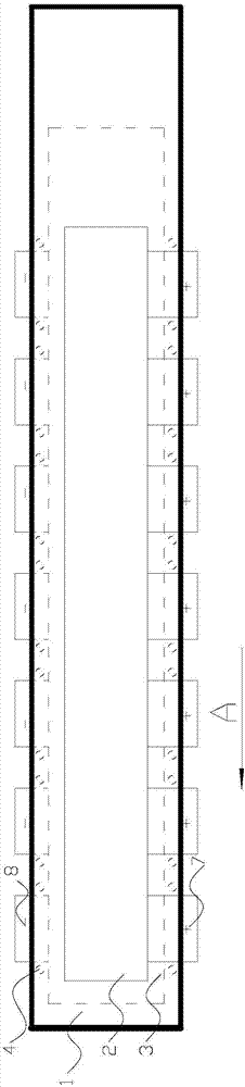
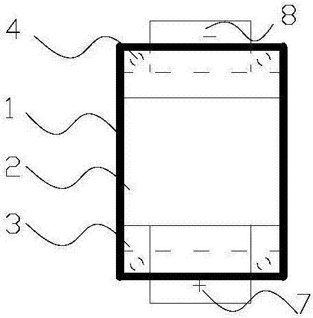
[0027] A high-temperature safe battery cell, comprising a diaphragm 1, a positive pole piece 2, and a negative pole piece 3, the diaphragm 1 is arranged at intervals between the positive pole piece 2 and the negative pole piece 3, and the positive pole piece 2 also includes a positive pole lug 7 , the negative pole piece 3 also includes a negative pole tab 8, the positive pole tab 7 and the negative pole tab 8 lead the positive pole piece 2 and the negative pole piece 3, and the other ends of the positive pole tab 7 and the negative pole tab 8 are located outside the diaphragm 1 . figure 1 It is a schematic diagram of the structure of a high-temperature safety battery before winding. The separator 1 is arranged in two layers horizontally. The negative electrode piece 3 is located between the two layers of separators 1. glued together, such as figure 2 As shown, the bonding point 4 is located outside the edge of the direction A of the negative electrode sheet 3, and the glue ...
Embodiment 2
[0029] Figure 4 It is a schematic diagram of Z-shaped lamination of a high-temperature safety battery cell. The rolled diaphragm 1 is set on the sizing platform 9, and the positive pole piece 2 and the negative pole piece 3 are arranged on the upper and lower sides of the diaphragm 1 at intervals, respectively. Carry out Z-shaped lamination, and glue and fix the upper and lower adjacent separators 1. The bonding point 4 is located on the edge of the separator 1 in the B direction, and the bonding point 4 is located outside the edge of the positive electrode sheet 2 or the negative electrode sheet 3. . Adjacent separators 1 are bonded by glue coating, and at least one bonding point 4 is provided on the edge of each separator 1 in the B direction. The structural diagram of the Z-shaped laminated high-temperature safety cell is shown in Figure 5 shown. Because of the special structure of the Z-shaped laminations, the left and right edges of the diaphragm 1 are wound with the ...
Embodiment 3
[0031] Image 6 It is a schematic diagram of a stacked structural unit 5 of a high-temperature safety battery. The stacked structural unit 5 includes a diaphragm 1, a positive pole piece 2, and a negative pole piece 3. The diaphragm 1 is horizontally arranged in two layers, and the negative pole pieces 3 are respectively arranged on the Between the two layers of separators 1, the positive pole piece 2 is respectively arranged above the first layer of separator 1 and below the second layer of separator 1, and the positions of the positive pole piece 2 and the negative pole piece 3 on both sides of the separator 1 correspond to form a battery pair. The two layers of diaphragm 1 are fixed by adhesive points 4, such as Figure 7 As shown, the bonding points 4 are located around the negative electrode sheet 3, and the two layers of separators 1 are glued or hot-melt bonded, and at least one bonding point 4 is provided on the outside of each side of the negative electrode sheet 3. ...
PUM
 Abstract
Description
Claims
Application Information
 - R&D
- Intellectual Property
- Life Sciences
- Materials
- Tech Scout
- Unparalleled Data Quality
- Higher Quality Content
- 60% Fewer Hallucinations
Browse by: Latest US Patents, China's latest patents, Technical Efficacy Thesaurus, Application Domain, Technology Topic, Popular Technical Reports.
© 2025 PatSnap. All rights reserved.Legal|Privacy policy|Modern Slavery Act Transparency Statement|Sitemap|About US| Contact US: help@patsnap.com