
Anti-freezing switch cabinet

A switchgear and cabinet body technology, applied in the field of switchgear, can solve problems such as cracking of the switchgear, freezing of the switchgear, performance change of the switchgear, etc., and achieve the effects of convenient installation and maintenance, high heating efficiency, and uniform heating

Inactive Publication Date: 2017-09-26
HEFEI SHANGQIANG ELECTRIC TECH CO LTD
View PDF7 Cites 1 Cited by
  • Summary
  • Abstract
  • Description
  • Claims
  • Application Information

AI Technical Summary

Problems solved by technology

[0004] A problem in some areas of our country is that the temperature in winter is relatively low, and the lowest temperature is even lower than minus 30 degrees Celsius. Therefore, the problem of low temperature is a common problem faced by switch cabinets in these areas; through long-term practice, it is found that the switch cabinets in these areas have the following Defects: 1. When the external ambient temperature is low, freezing weather often occurs, especially in winter rainy or snowy weather conditions, the ice accumulation on the switchgear and the inside of the switchgear freeze, resulting in changes in the performance of the switchgear , so as to increase the load of the switchgear, and even cause the defect of the switchgear to crack; 2. The low temperature condition will cause the performance of the operating parts of the switchgear to decline, and at the same time cause more troublesome maintenance

Method used


Image

  • Anti-freezing switch cabinet
  • Anti-freezing switch cabinet
  • Anti-freezing switch cabinet

Examples


Embodiment 1

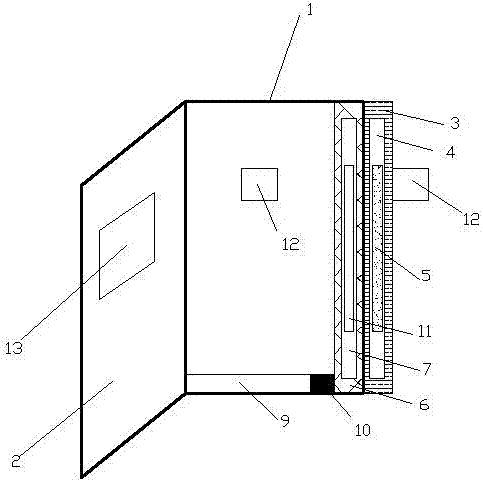
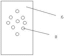
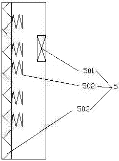
[0029] see figure 1 , figure 2 , image 3 , this embodiment relates to an antifreeze switchgear, comprising a cabinet body 1 and a cabinet door 2, the outer wall of the cabinet body 1 is provided with a thermal insulation board 3, and the thermal insulation board 3 is provided with a heating device accommodating cavity 4, and the heating device accommodating cavity 4. A heating device 5 is provided inside, and the heating device 5 includes a control unit 501, an excitation unit 502 and an induction unit 503. The inner wall of the cabinet body 1 is provided with a heat dissipation layer 6, and the heat dissipation layer 6 is provided with a heat dissipation pipe accommodating cavity 7. The heat dissipation pipe 11 hovers inside the heat dissipation pipe accommodation cavity 7. The heat dissipation layer 6 is provided with a heat dissipation hole 8 connecting the inner cavity of the cabinet body 1 and the heat dissipation pipe accommodation chamber 7. The bottom of the cabinet...

Embodiment 2

[0039] see figure 1 , figure 2 , image 3 , this embodiment relates to an antifreeze switchgear, comprising a cabinet body 1 and a cabinet door 2, the outer wall of the cabinet body 1 is provided with a thermal insulation board 3, and the thermal insulation board 3 is provided with a heating device accommodating cavity 4, and the heating device accommodating cavity 4. A heating device 5 is provided inside, and the heating device 5 includes a control unit 501, an excitation unit 502 and an induction unit 503. The inner wall of the cabinet body 1 is provided with a heat dissipation layer 6, and the heat dissipation layer 6 is provided with a heat dissipation pipe accommodating cavity 7. The heat dissipation pipe 11 hovers inside the heat dissipation pipe accommodation cavity 7. The heat dissipation layer 6 is provided with a heat dissipation hole 8 connecting the inner cavity of the cabinet body 1 and the heat dissipation pipe accommodation chamber 7. The bottom of the cabinet...

Embodiment 3

[0051] see figure 1 , figure 2 , image 3 and Image 6 , this embodiment relates to an antifreeze switchgear, comprising a cabinet body 1 and a cabinet door 2, the outer wall of the cabinet body 1 is provided with a thermal insulation board 3, and the thermal insulation board 3 is provided with a heating device accommodating cavity 4, and the heating device accommodating cavity 4. There is a heating device 5 inside. The heating device 5 includes a control unit 501, an excitation unit 502 and an induction unit 503. The inner wall of the cabinet body 1 is provided with a heat dissipation layer 6, and the heat dissipation layer 6 is provided with a heat dissipation pipe accommodation chamber. 7. The heat dissipation pipe 11 hovers inside the heat dissipation pipe accommodation cavity 7. The heat dissipation layer 6 is provided with a heat dissipation hole 8 connecting the inner cavity of the cabinet body 1 and the heat dissipation pipe accommodation chamber 7. The bottom of th...


PUM

PropertyMeasurementUnit
Diameteraaaaaaaaaa
Diameteraaaaaaaaaa

Abstract

The invention discloses an anti-freezing switch cabinet. The anti-freezing switch cabinet comprises a cabinet body and a cabinet door, wherein a thermal insulation plate is arranged on the outer wall of the cabinet body; a heating device accommodating cavity is formed in the thermal insulation plate; a heating device is arranged in the heating device accommodating cavity and comprises a control unit, a excitation unit and a sensing unit; a heat dissipation layer is arranged on the inner wall of the cabinet body; a heat dissipation pipe accommodating cavity is formed in the heat dissipation layer, a heat dissipation pipe is coiled in the heat dissipation pipe accommodating cavity; heat dissipation holes for communicating an inner cavity of the cabinet body with the heat dissipation pipe accommodating cavity are formed in the heat dissipation layer; a liquid storage chamber is formed in the bottom of the cabinet body; a water pump is arranged on the liquid storage chamber and controls a liquid to circulate between the liquid storage chamber and the heat dissipation pipe; temperature sensors are arranged between the inner cavity of the cabinet body and the outer wall of the cabinet body, and the temperature sensors, the heating device and the water pump are in signal connection with a controller located on the cabinet door. The anti-freezing switch cabinet realizes uniform heating, and is high in heating efficiency, low in fault rate and suitable for being popularized.

Description

technical field [0001] The invention relates to the technical field of switch cabinets, in particular to an antifreeze switch cabinet. Background technique [0002] The switch cabinet is a kind of electrical equipment. The outside line of the switch cabinet first enters the main control switch in the cabinet, and then enters the sub-control switch. Each branch is set according to its needs. Such as instruments, automatic controls, motor magnetic switches, various AC contactors, etc., some also have high-voltage room and low-voltage room switch cabinets, high-voltage busbars, such as power plants, etc. load shedding. [0003] The main function of the switchgear is to open and close, control and protect electrical equipment during the process of power generation, transmission, distribution and power conversion in the power system. The components in the switch cabinet are mainly composed of circuit breakers, disconnectors, load switches, operating mechanisms, transformers and...

Claims


Application Information

Patent Timeline
IPC IPC(8): H02B1/56
CPCH02B1/565
Inventor 程劲松
Owner HEFEI SHANGQIANG ELECTRIC TECH CO LTD
Learn More