Unmanned ship with electromagnetic interference detection function and electromagnetic interference coping method
An electromagnetic interference and anti-electromagnetic interference technology, applied in the direction of communication interference, electrical components, etc., can solve the problems of the unmanned ship's anti-electromagnetic interference method is rigid and cannot effectively overcome the channel frequency band electromagnetic interference attack.
- Summary
- Abstract
- Description
- Claims
- Application Information
AI Technical Summary
Problems solved by technology
Method used
Image
Examples
Embodiment 1
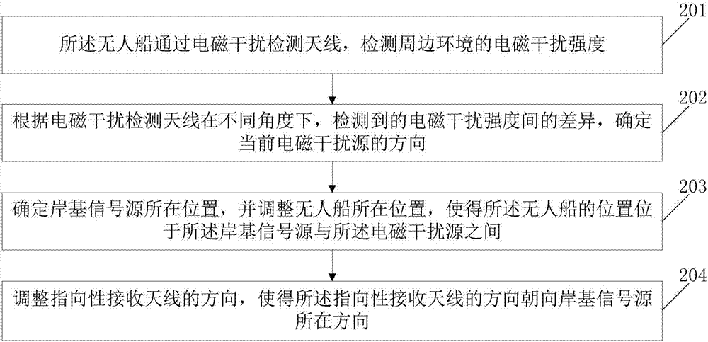
[0050] Embodiment 1 of the present invention provides a method for dealing with electromagnetic interference based on an unmanned ship. When the unmanned ship is determined to be subjected to electromagnetic interference, the method for dealing with electromagnetic interference is activated. Among them, the determination of electromagnetic interference by the unmanned ship can be confirmed when it sends a request message to the shore base but does not receive a response signal, or it is confirmed when the GPS positioning equipment on the unmanned ship cannot receive the positioning signal from the satellite. It may also be that the unmanned ship sends a request message to the control center in the unmanned ship cluster but does not receive a response message and confirms that it has received electromagnetic interference. like figure 1 As shown, the method for dealing with electromagnetic interference includes the following steps:
[0051] In step 201, the unmanned ship detects ...
Embodiment 2
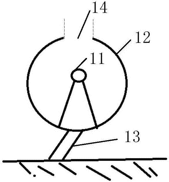
[0066] For the electromagnetic interference detection antenna 1 proposed in embodiment 1, how to use its adjustment rod 13 to adjust the antenna 11 and the gap 14 to detect the electromagnetic interference signal source, only describes its detectable range, but does not give a specific detection method. The embodiment of the invention provides the most efficient detection method, such as Figure 7 As shown, step 202 in the embodiment is specifically implemented as, specifically including:
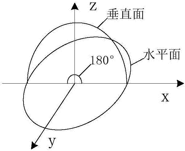
[0067] In step 301, the unmanned ship controls the orientation of the received signal of the electromagnetic interference detection antenna to be in the horizontal direction, and controls the orientation of the received signal to rotate 360° in the horizontal direction.
[0068] Wherein, the 360° area in the horizontal direction can be set according to the size of the notch 14, specifically: according to the diameter of the notch 14 and the proportional relationship between the diameter and...
Embodiment 3
[0075]In Embodiment 1, an implementation method is provided to make the position of the unmanned ship be located between the shore-based signal source and the electromagnetic interference signal source. However, for the actual situation, it is necessary to realize the It may be difficult to move between the shore-based signal source and the electromagnetic interference signal source. On the other hand, this intuitive emergency method can be easily confirmed by the enemy as the current unmanned ship has been effectively attacked by electromagnetic interference. . Therefore, in the embodiment of the present invention, in step 203 of step 1, the position of the unmanned ship is adjusted so that the position of the unmanned ship is located between the shore-based signal source and the electromagnetic interference signal source, and there is more In order to be effective and able to deal with more complex electromagnetic interference attacks, such as Figure 8 shown, including the...
PUM
 Abstract
Description
Claims
Application Information
 - R&D
- Intellectual Property
- Life Sciences
- Materials
- Tech Scout
- Unparalleled Data Quality
- Higher Quality Content
- 60% Fewer Hallucinations
Browse by: Latest US Patents, China's latest patents, Technical Efficacy Thesaurus, Application Domain, Technology Topic, Popular Technical Reports.
© 2025 PatSnap. All rights reserved.Legal|Privacy policy|Modern Slavery Act Transparency Statement|Sitemap|About US| Contact US: help@patsnap.com


